McIDAS-X Learning Guide
Version 2020
[Search Manual] [Table of Contents] [Go to Previous] [Go to Next]
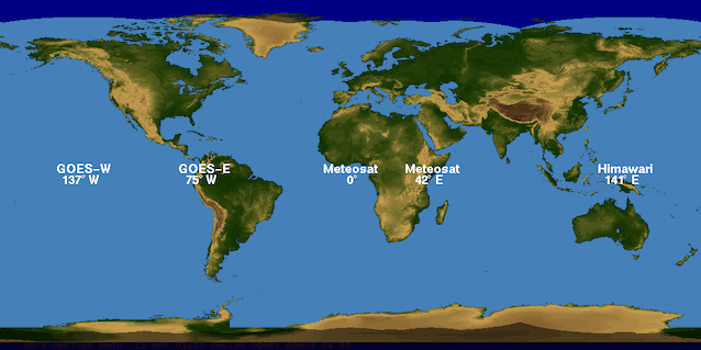
SSEC receives real-time satellite images from geostationary and polar orbiting satellites. Geostationary satellites remain above a fixed location on the earth's surface, appoximately 35,800 km above the equator. Because the satellites rotate with the earth, they always observe the same portion of the globe. Typically, there are operational geostationary satellites from the United States, the European Organisation for the Exploitation of Meteorological Satellites (EUMETSAT), and the Japan Meteorological Agency (JMA).
At most times, the United States has a satellite called GOES-East, which monitors North and South America and the western Atlantic Ocean, and one called GOES-West, which monitors North and South America and the eastern Pacific Ocean. EUMETSAT has two satellites (METEOSAT) which monitor Europe, Africa, Asia, the Indian Ocean, and the Atlantic Ocean. JMA has a satellite (Himawari) which monitors eastern Asia, Australia, the western Pacific Ocean and the eastern Indian Ocean.
Roll your mouse over the image below to see the coverage of each geostationary satellite:
Polar orbiting satellites orbit at much lower altitudes (800-900 km). Their path is 2,400 km wide centered at the orbit path. With each orbit, the satellites observe a new path. SSEC typically receives real-time imagery from the operational POES satellites plus others like Metop, Aqua and Terra.
See the SSEC Satellite Data Service's website for a list of all current, archived (goes) and archived (non-goes) satellite data available from SSEC.
Type: HELP DSSERVE
When copying satellite data locally to your machine for use in McIDAS, the resulant file format is called Area. You can copy, change, display, and delete Area files. Area files contain both data and area directories, similar to how each satellite server assembles the data in memory for use in McIDAS. These satellite data can be displayed in McIDAS image frames. The server or area directory contains descriptive information, such as the sensor source, image date, picture start time, and image coordinates. To see this information, use the IMGLIST command, as shown below to list a mission-standard Level 1b file in netCDF-4 format setup in a dataset which is using the ABIN server format:
IMGLIST G16C.1 FORM=ALL
Image file directory listing for:G16C
 Pos Satellite/         Date       Time      Center      Res (km)   Image_Size
     sensor                                 Lat  Lon    Lat   Lon
 --- -------------  ------------  --------  ---- ----  ----- ----- ------------
   1  GOES-16       14 SEP 19257  10:51:13    30   87
   Band: 1    0.47 um VIS aerosol-over-land             1.00  1.00  3000 x 5000
   Band: 2    0.64 um VIS clouds fog, insol, winds      0.50  0.50  6000 x10000
   Band: 3    0.86 um Near IR veg/burn scar,aerosol, w  1.00  1.00  3000 x 5000
   Band: 4    1.37 um Near IR cirrus cloud              2.00  2.00  1500 x 2500
   Band: 5    1.6 um Near IR cloud phase, snow          1.00  1.00  3000 x 5000
   Band: 6    2.2 um Near IR land/cloud, vege, snow     2.00  2.00  1500 x 2500
   Band: 7    3.9 um IR Sfc, cloud, fog, fire, winds    2.00  2.00  1500 x 2500
   Band: 8    6.2 um IR High-level WV, winds, rainfall  2.00  2.00  1500 x 2500
   Band: 9    6.9 um IR Mid-level WV, winds, rainfall   2.00  2.00  1500 x 2500
   Band: 10   7.3 um IR Lower-level WV, winds & SO2     2.00  2.00  1500 x 2500
   Band: 11   8.4 um IR Total WV cloud phase, dust      2.00  2.00  1500 x 2500
   Band: 12   9.6 um IR Total ozone,turbulence,wind     2.00  2.00  1500 x 2500
   Band: 13   10.3 um IR Surface & cloud                2.00  2.00  1500 x 2500
   Band: 14   11.2 um IR Imagery,SST,clouds,rainfall    2.00  2.00  1500 x 2500
   Band: 15   12.3 um IR Total water, ash, and SST      2.00  2.00  1500 x 2500
   Band: 16   13.3 um IR Air temp, cloud hgt and amt    2.00  2.00  1500 x 2500
     proj:    0 created: 2019257 105113  memo: GOES ConUS - Mode 6
     type:ABIN     cal type:RAW
     offsets:  data=    1280 navigation=  256 calibration=  768 auxiliary= 0
     doc length:   0   cal length:   0   lev length:   0 PREFIX=   0
     valcod:          0 zcor:  0 avg-smp: A
     lcor:    1  ecor:     1  bytes per pixel: 2  ss:186
     Resolution Factors (base=1):   Line=    4.0   Element=    4.0
IMGLIST: done
|
Area files use the naming convention AREAnnnn where nnnn is the four digit area number. For example, AREA0003 is the name of the file that contains area 3. In ADDE, sequences of Area files are grouped together in a dataset. For example, in a previous lesson, you created the dataset MYDATA/IMAGES, which contains the Area file numbers from 1 to 9999. Individual Area files can be accessed with their position number within the dataset. In the case of MYDATA/IMAGES, position 3 (MYDATA/IMAGES.3) would relate to the file AREA0003. However, in the dataset MYDATA/TEST-IMAGES that was created in the previous lesson, the dataset defined the Area files ranging from 4000 to 4004, so position 3 (MYDATA/TEST-IMAGES.3) would be AREA4002. (This would be equivalent to MYDATA/IMAGES.4002)
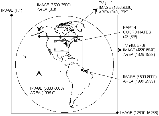
Navigation, as applied to satellite imagery, means the conversion between satellite image coordinates (line and element) and earth coordinates (latitude and longitude). This is usually done when the data is ingested.
If a displayed image sector is navigated, McIDAS can convert the image coordinates of a specified pixel to earth coordinates. The E command lists the earth, TV and image coordinates at the cursor center.
Image resolution is measured in kilometers and is highest at the subsatellite point. The highest available resolution depends on the satellite, band and image type:
Satellite Visible Infrared GOES 0.5 km 2 km HIMAWARI 0.5 km 2 km MODIS 0.25 km 1 km MSG 1 km 3 km
POES 1 km 1 km
This means that a single GOES infrared pixel at the subsatellite point represents a 2km x 2km square on the earth's surface, and a single MSG visible pixel at the subsatellite point represents a 1km x 1km square on the earth's surface, etc. The further a pixel is located from the subsatellite point, the lower its resolution.
You can display imagery at a resolution other than that stored in the Area. Specifying a positive magnification factor in McIDAS commands (e.g., IMGDISP) enlarges or blows up the data by replicating pixel values; a negative magnification factor produces a blow down by sampling pixel values. For example, if you choose a magnification factor of 16, the value of each pixel in the Area is duplicated 256 times (in a 16 x 16 box of pixels) when displayed on the frame. If you choose a magnification factor of -4, the value of every fourth element along every fourth line is displayed as one pixel on the image frame.
[Search Manual] [Table of Contents] [Go to Previous] [Go to Next]