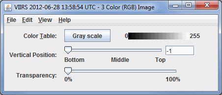
Image 1: Three Color (RGB) Image
The following describes each formula included in the Imagery Formulas section of McIDAS-V.
Note: If the formula you select utilizes a Select Input window to enter values to be used by the formula, you can choose if you want to save these values in a bundle if you wish to create one. Each field of the Select Input window has a Save in Bundle option (chosen by default). If you keep this option selected, the value(s) you choose will be stored in the bundle, and if all values are saved, the formula will automatically execute when you load in your bundle without any user input. If you do not save the values in your bundle, the values you use will not be saved, and the formula will not automatically execute without requiring the user to enter/change values.
Geolocate an Image (Upper Left Lat, Upper Left Lon, Lower Right Lat, Lower Right Lon) - Takes an image data object and a lat/lon bounding box and adds a lat/lon domain to the data. This formula is commonly used in conjunction with another formula.
| Input Parameter | Definition | |
Upper Left Lat |
Upper left latitude value (default=90). |
|
Upper Left Lon |
Upper left longitude value (default=-180). |
|
Lower Right Lat |
Lower right latitude value (default=-90). |
|
Lower Right Lon |
Lower right longitude value (default=180). |
|
Image over topography - Obtains the latitude coordinate from the grid and returns a grid of the latitudes at each point.
Mask Function - Allows you to specify a threshold value where only data greater than, less than, greater than or equal to, less than or equal to, or equal to values will display. After defining the initial Input Parameters, a Field Selector window will appear where you can specify inputFieldForMask (the field to be masked) as well as displayFieldToBeMasked (a second field that will be multiplied by the result of the mask of the inputFieldForMask. This field can be either the same field that you apply the mask to, or a different field).
| Input Parameter | Definition | |
comparison |
The mathematical operator applied to the cutoff value to determine which data values are displayed. |
|
cutoff |
The numerical boundary that will be applied to the comparison value. |
|
useNaN |
Default value = 1. When 0, values outside data will be 0, when 1, values outside data will be unprobeable. |
|
Mask Within Range - Allows you to specify a numerical range where data values will display. After defining the initial Input Parameters, a Field Selector window will appear where you can specify inputFieldForMask (the field to be masked) as well as displayFieldToBeMasked (a second field that will be multiplied by the result of the mask of the inputFieldForMask. This field can be either the same field that you apply the mask to, or a different field).
| Input Parameter | Definition | |
minValue |
The minimum data value that will be displayed. |
|
maxValue |
The maximum data value that will be displayed. |
|
useNan |
Default value = 0. When 0, values outside data will be 0, when 1, values outside data will be unprobeable. |
|
Scale images to brightness ranges - Displays your selected parameter in the Main Display window. Instead of using the color bar range that would be customary for your selected parameter, the standard range for brightness values will be used (i.e. 0-255).
Three Color (RGB) Image - Combines three images as a RGB image when the 3 Color (RGB) Image display type is selected. When you select Create Display, a Field Selector window will open. The fields in this window are red, green, and blue. Once you click OK, an RGB image will be created in the Main Display window. Below is the Layer Controls tab for the 3 Color (RGB) Image display type.

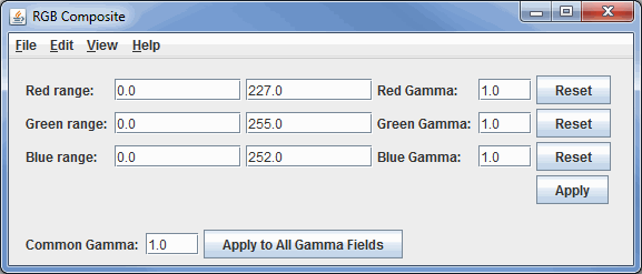
Three Color (RGB) Image (Auto-scale) - Combines three images as a RGB image when the RGB Composite display type is selected. When you select Create Display, a Field Selector window will open. The fields in this window are red, green, and blue. Once you click OK, an RGB image will be created in the Main Display window. After the display is created, you have the ability to change the ranges for the red, green, and blue values, as well as the gamma values. Below is the Layer Controls tab for the RGB Composite display type.
