MR Interferometer Installation
Tools and Equipment Required
- Small phillips screwdriver
- Small flathead screwdriver
- 2.5 mm metric hex driver
- 1/4″ hex driver
Precaution
- The interferometer is fairly heavy, and should be lifted by two people
- Be careful in sliding the interferometer front window into the tube on the back-end
- Verify that the interferometer is correctly seated in the kinematic mount
- Be careful to not perturb the screws on the kinematic mount that optically aligns the interferometer
Procedure
- Confirm that the AERI back-end is powered OFF
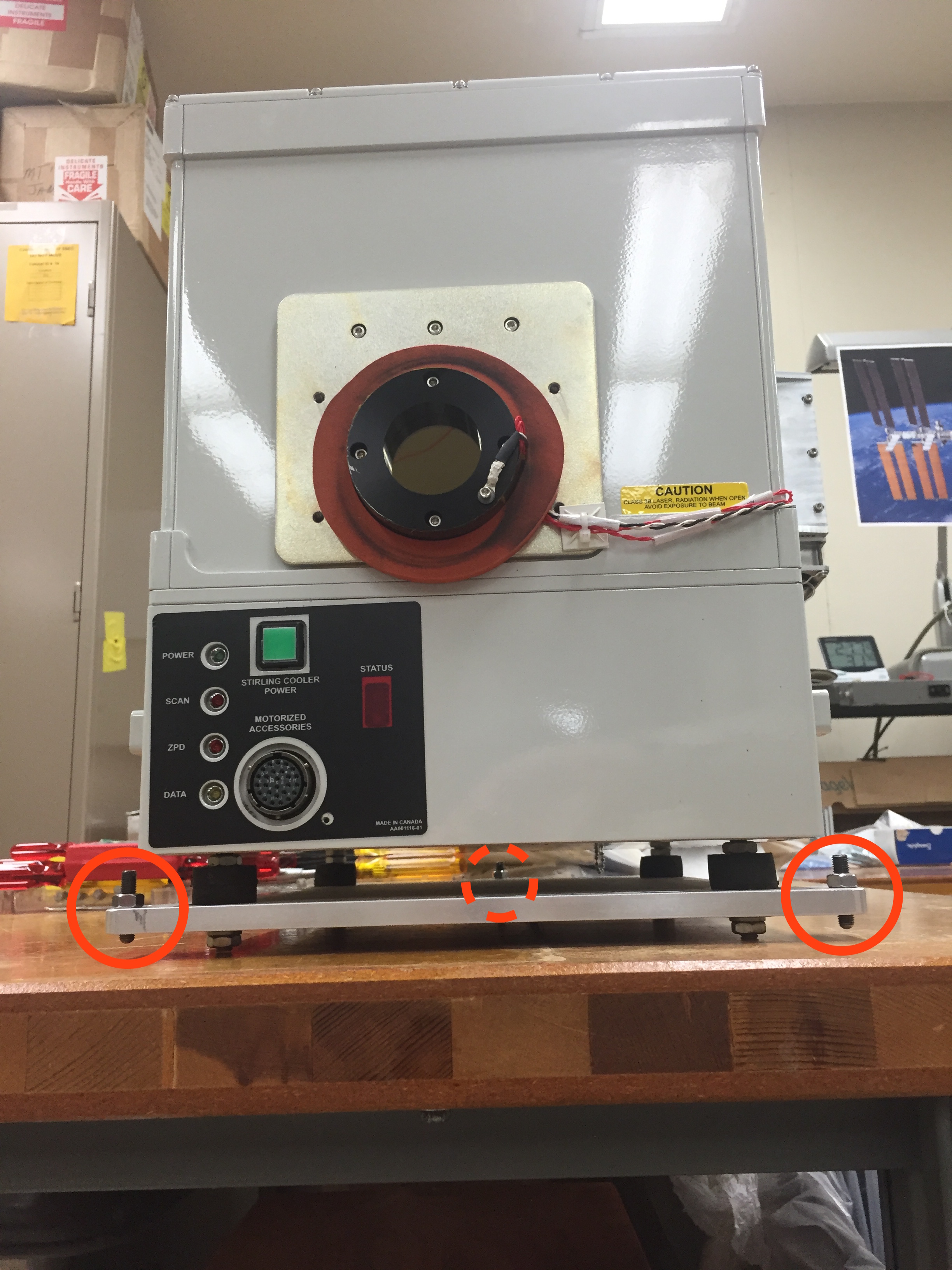
- Examine the MR interferometer. Ensure that the front gaskets are properly seated on the front window around. Note the 3 posts for the kinematic mount (Fig. 1).
- Examine the AERI back-end. Note the 3 receptacles for the kinematic mount (socket, slot, flat). Note the tube that the interferometer front window needs to slide into. Ensure the motor controller is removed, for ease of installation of the interferometer (Fig. 2).
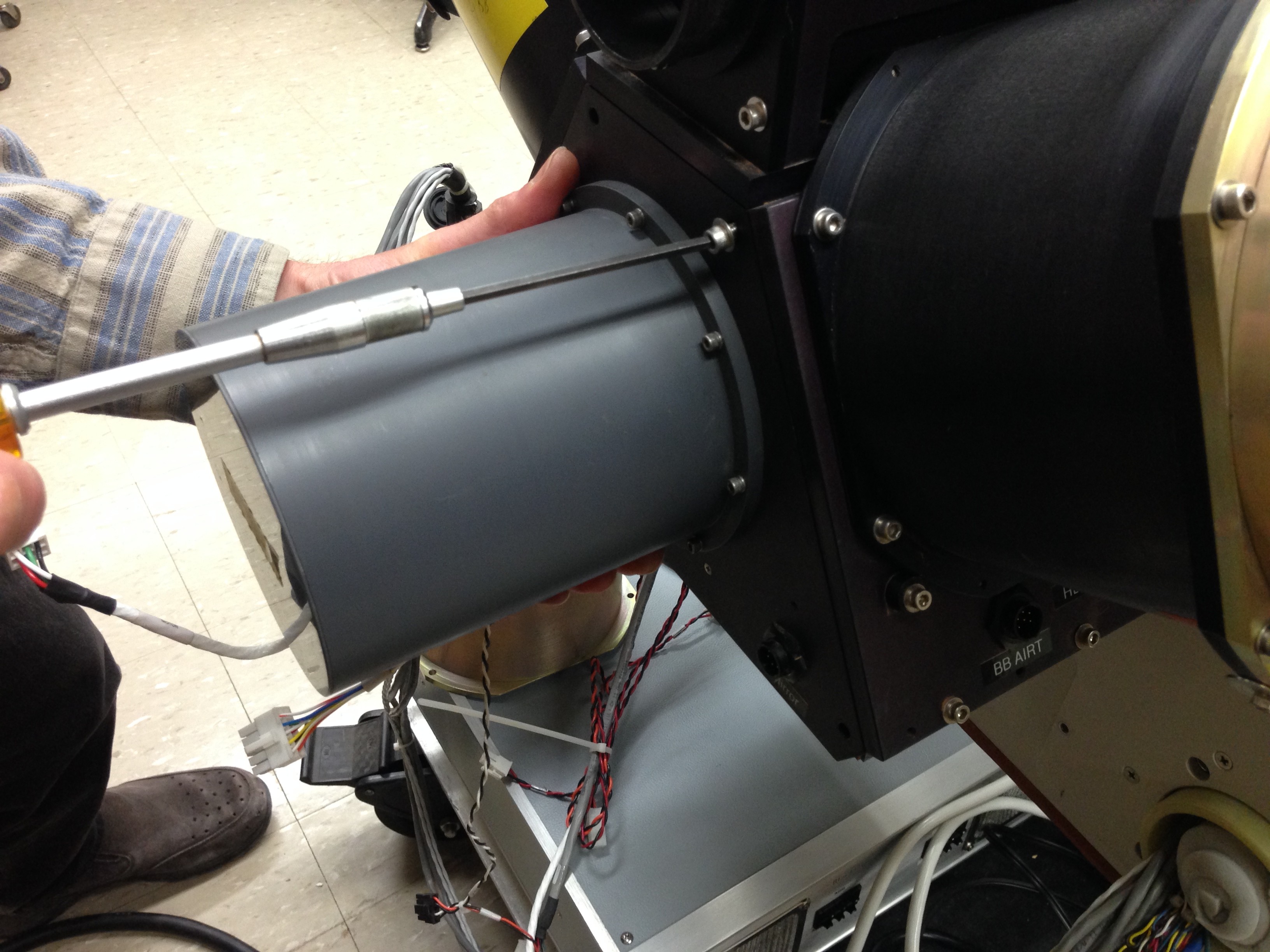
- Carefully lift the interferometer and place onto the back-end. The front-window needs to carefully slide into the tube on the back-end. The interferometer needs to rest correctly in the kinematic mount.
- The front-right post has to be fully inside the socket
- The front-left post has to be fully inside the slot
- The rear-center post will sit on the flat receptacle
- Verify the the front window gasket is compressed between the interferometer and the back wall of the back-end. There should be no air gap between the gasket and the two surfaces. If a gap is present and the gasket is not compressed, then an additional (thicker) gasket must be added.
- Secure the MR holder plate to the back-end using the three 1/4″ hex screws provided with the back-end. Note: do not touch the nuts/screws for the kinematic mount (Fig. 3).
- Reconnect the 11 electrical connections to the MR interferometer (Figs. 4, 5).
| Name | Label | Connector | Notes | |
|---|---|---|---|---|
| 1 | Power cable | MR 28V | Milspec | |
| 2 | Ethernet cable | MRXS | RJ45 | |
| 3 | Cooler diode cable | Sens2MR | Metallic screw+ground | Attach ground wire to screw in cooler expander |
| 4 | Sens 1MR | Plastic 5-pin | ||
| 5 | Cooler expander thermistor | CoolerT | 5-pin | |
| 6 | Cooler expander fan cable | Cool fan | 2-pin | |
| 7 | Cooler compressor fan cable | Comp fan | 2-pin | |
| 8 | Cooler power | Cool | 6-pin | |
| 9 | Cooler compressor thermistor | SCCTEMP | Screw lug | Attach thermistor lug to screw in cooler compressor heat sink; 2.5 mm metric driver needed |
| 10 | Cooler controller cable | Cool Ctrl | 20?-pin + ground | Attach ground wire to screw in cooler compressor heat sink; 2.5 mm metric driver needed |
| 11 | Front window heater and thermistor | S Window | 6-pin |
Figure 1. MR interferometer, indicating locations of kinematic mount posts
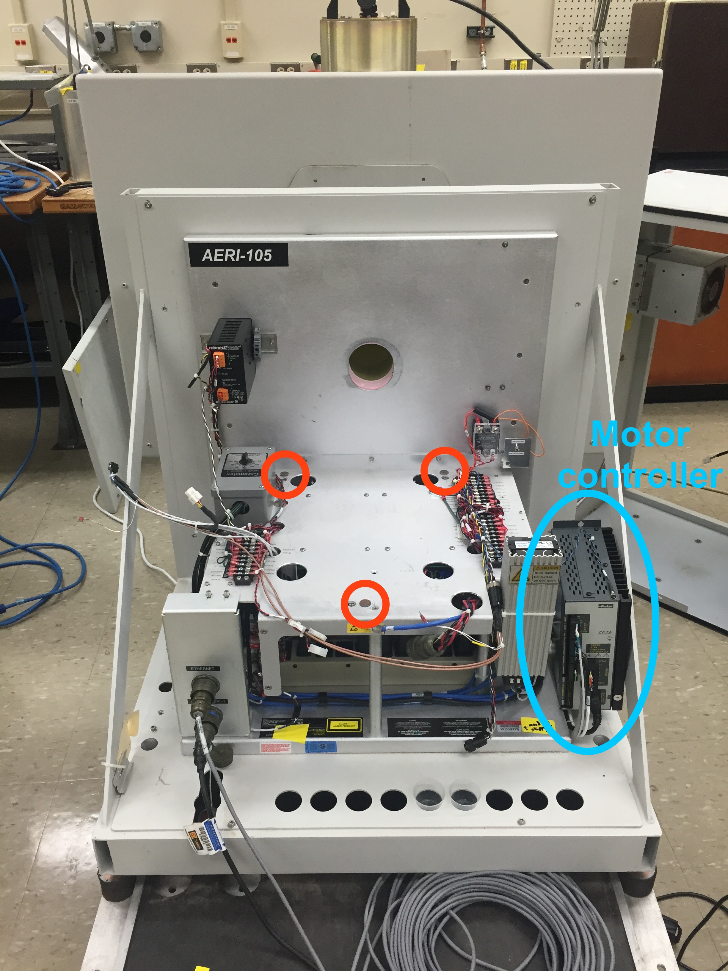
Figure 2. Back-end, indicating locations of kinematic mount receptacles. Note removed motor controller.
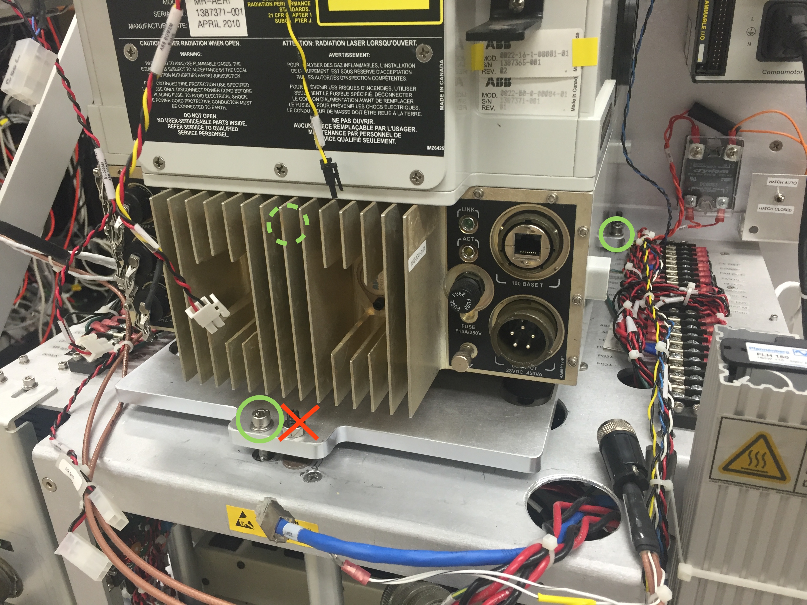
Figure 3. Three socket-head cap screws holding the MR unit to the back-end
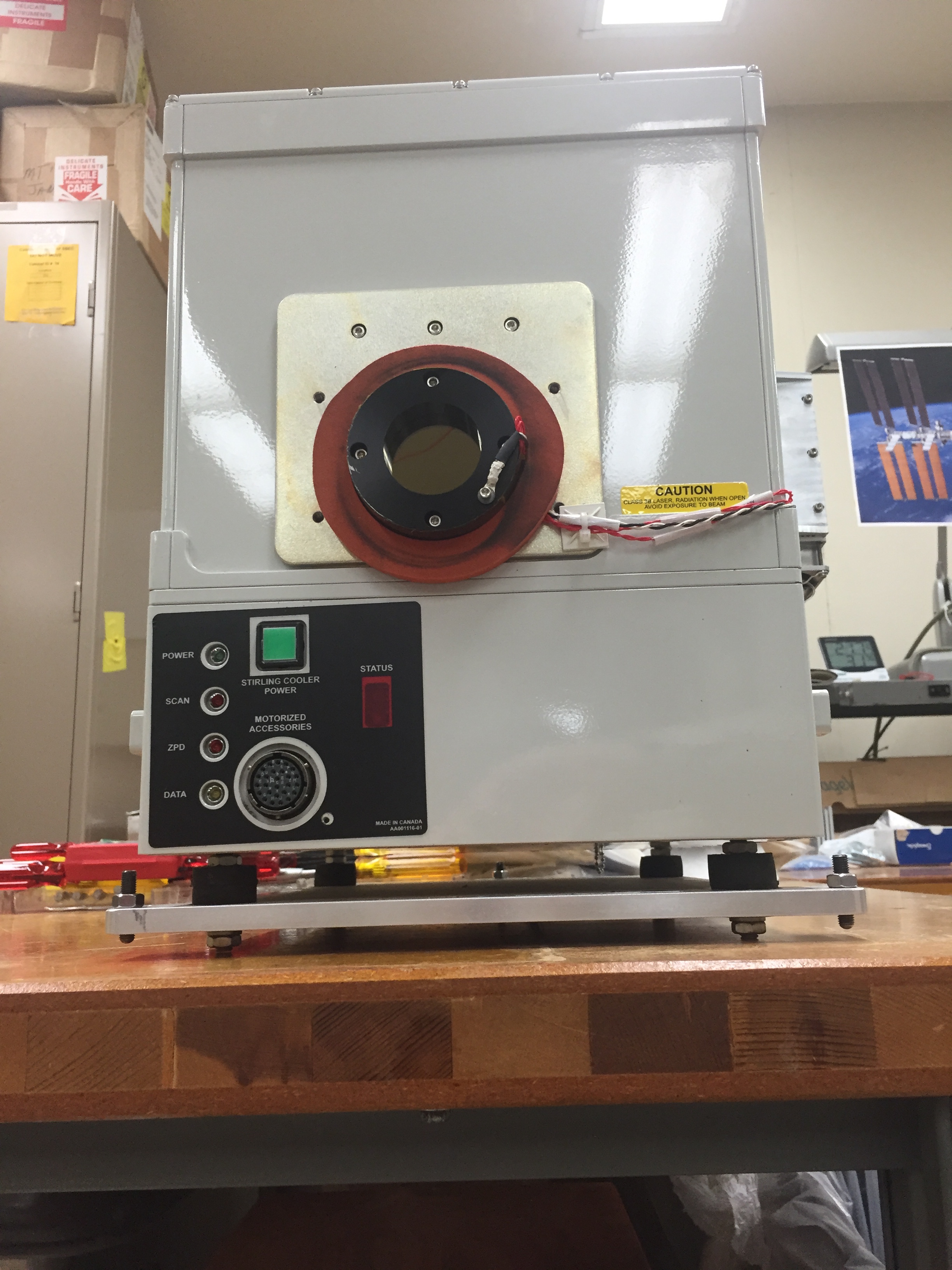
Figure 4. MR electrical connections 1-8 to connect
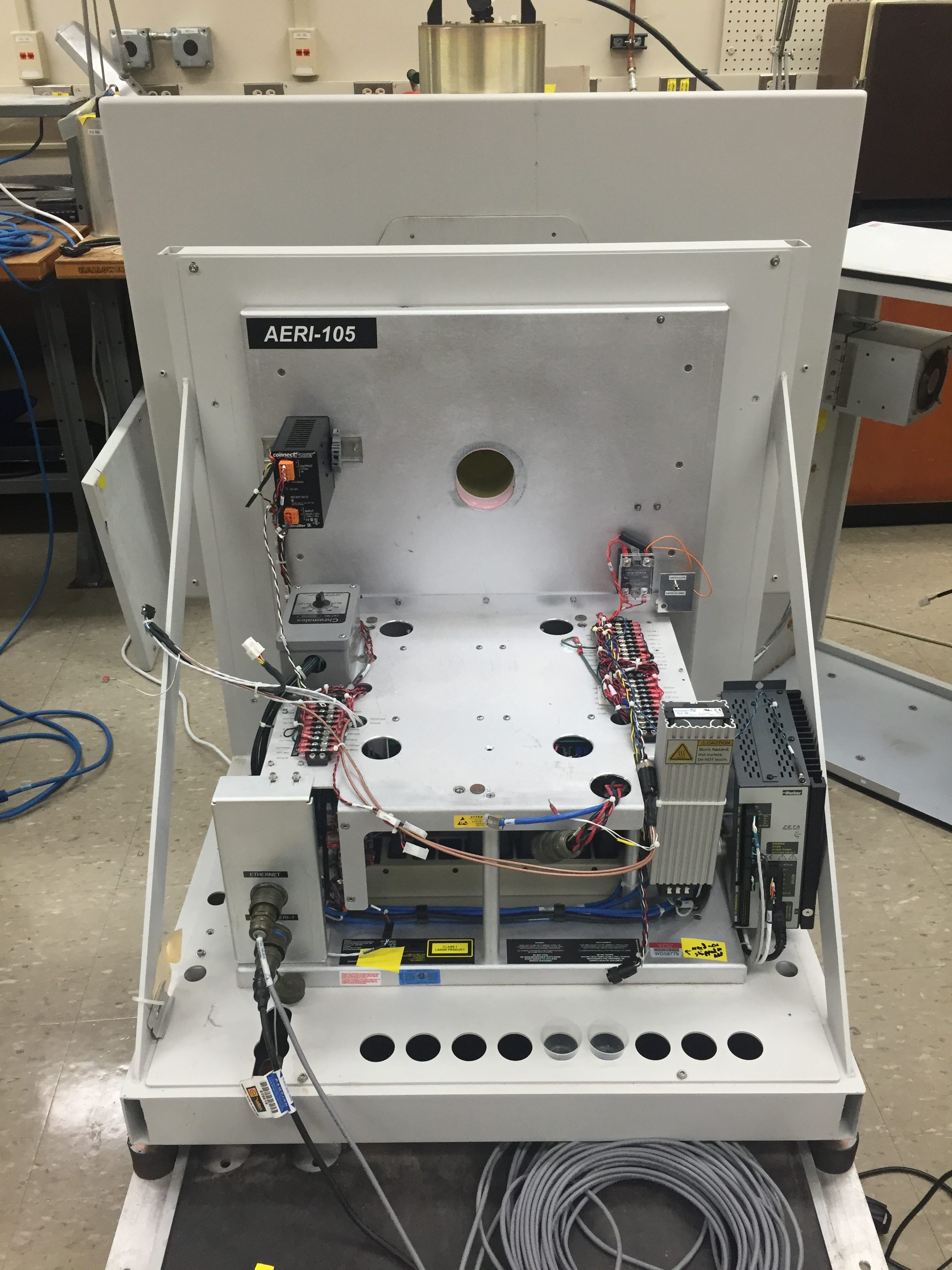
Figure 5. MR electrical connections 9-11 to connect