MR Interferometer Removal
Tools and Equipment Required
- Small phillips screwdriver
- Small flathead screwdriver
- 2.5 mm metric hex driver
- 1/4″ hex driver
Precaution
- The interferometer is fairly heavy, and should be lifted by two people
- Be careful in sliding out the interferometer front window from the tube in the back-end
- Be careful to not perturb the screws on the kinematic mount that optically aligns the interferometer
Procedure
- Stop data collection and power off the instrument.
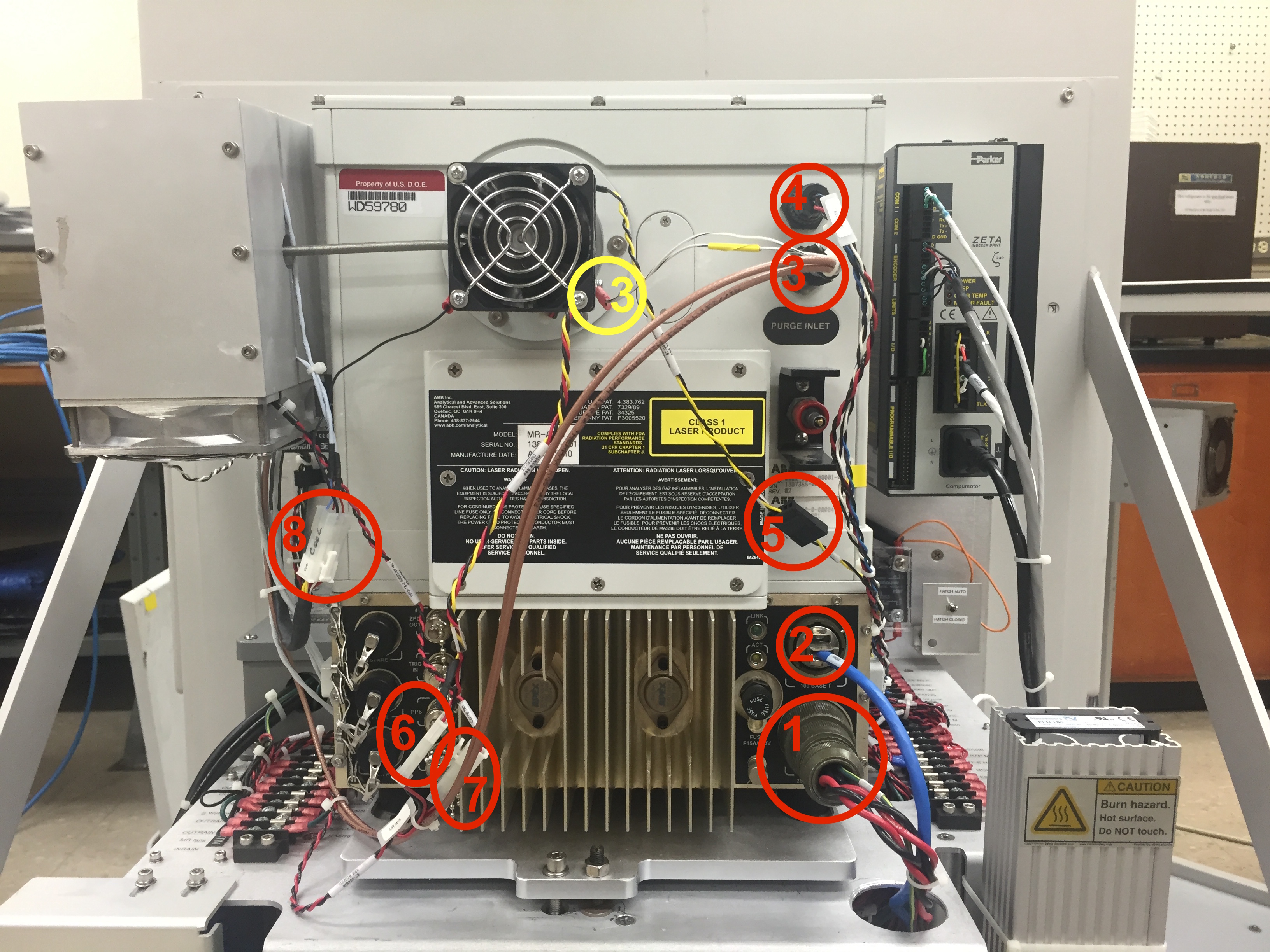
- Disconnect the 11 electrical connections between the MR unit and the back-end (Figs. 1, 2):
| Name | Label | Connector | Notes | |
|---|---|---|---|---|
| 1 | Power cable | MR 28V | Milspec | |
| 2 | Ethernet cable | MRXS | RJ45 | |
| 3 | Cooler diode cable | Sens2MR | Metallic screw+ground | Leave ground screw in place after removing ground wire |
| 4 | Sens 1MR | Plastic 5-pin | ||
| 5 | Cooler expander thermistor | CoolerT | 5-pin | Disconnect at connector; leave screw and thermistor in place |
| 6 | Cooler expander fan cable | Cool fan | 2-pin | |
| 7 | Cooler compressor fan cable | Comp fan | 2-pin | |
| 8 | Cooler power | Cool | 6-pin | |
| 9 | Cooler compressor thermistor | SCCTEMP | Screw lug | 2.5 mm metric driver needed; leave screw in place after removing thermistor |
| 10 | Cooler controller cable | Cool Ctrl | 20?-pin + ground | Disconnect at connector (do not remove controller); 2.5 mm metric driver needed; leave ground screw in place after removing ground wire |
| 11 | Front window heater and thermistor | S Window | 6-pin |
- Unscrew the MR holder plate from the back-end using the three 1/4″ hex screws (Fig. 3). Note: do not touch the nuts/screws for the kinematic mount.
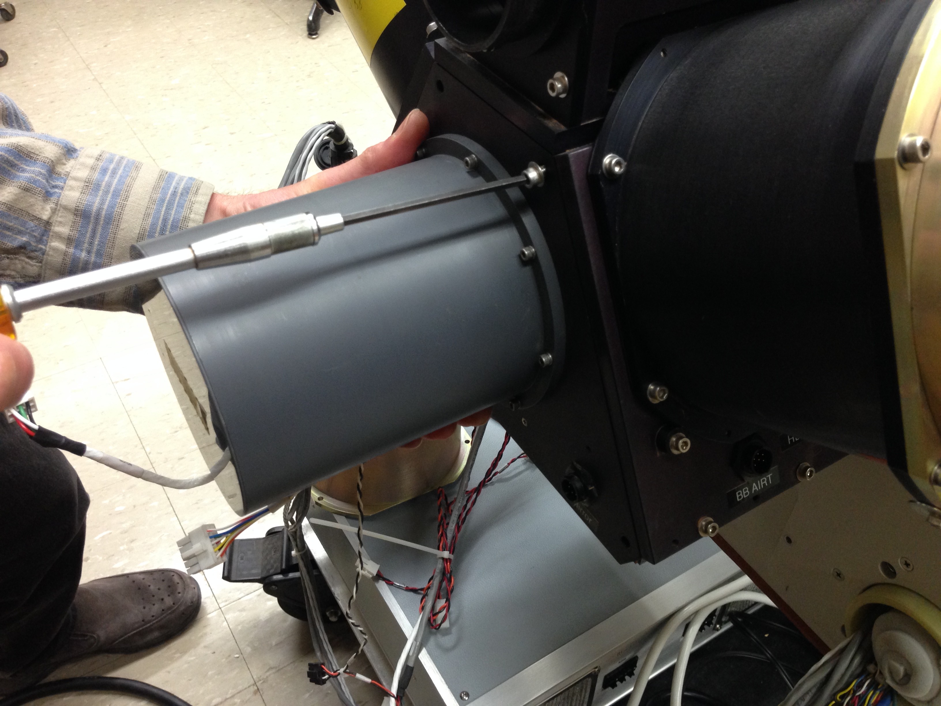
- Carefully remove the MR unit. Note: It helps to temporarily remove the motor controller to have better access. Note: the front window slides into a tube on the back-end; take care to slide the window out prior to lifting (Figs 4, 5).
- Inspect the front window, gasket, heather and thermistor for damage or wear and tear.
- Cover the front window aperture to protect the window.
- The three 1/4″ hex screws should stay with the AERI back-end.
Figure 1. MR electrical connections 1-8 to disconnect
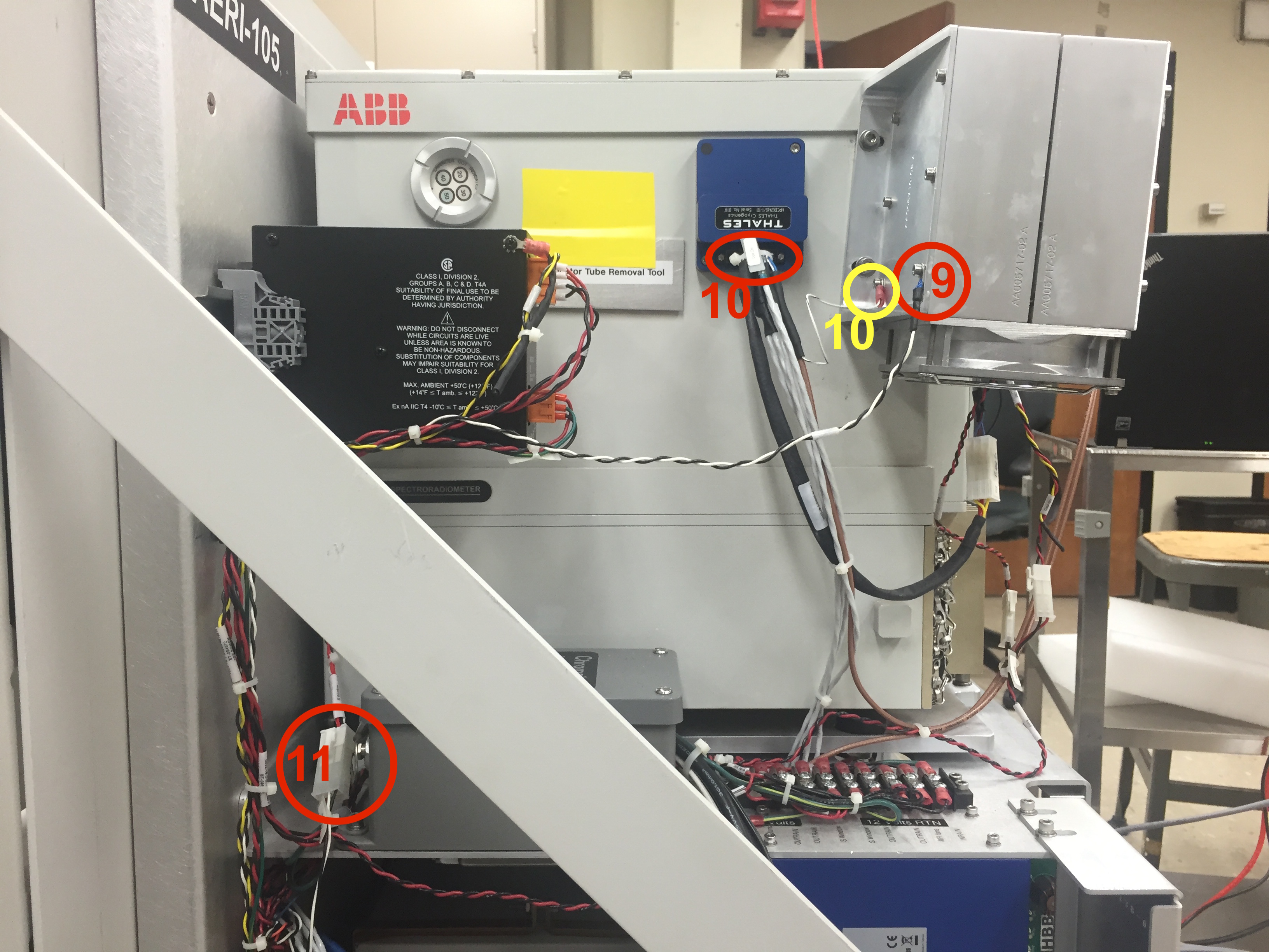
Figure 2. MR electrical connections 9-11 to disconnect
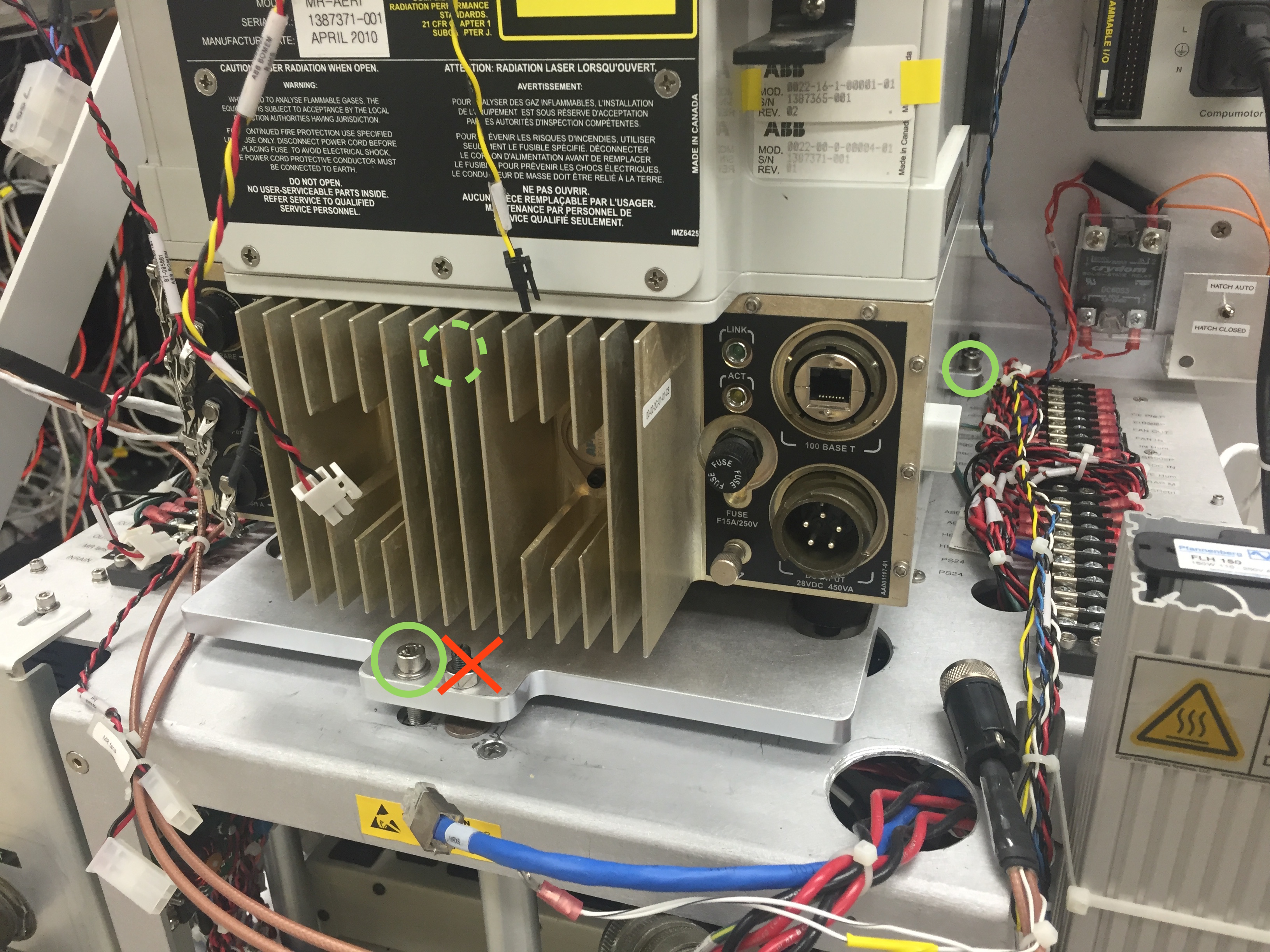
Figure 3. Three socket-head cap screws holding the MR unit to the back-end
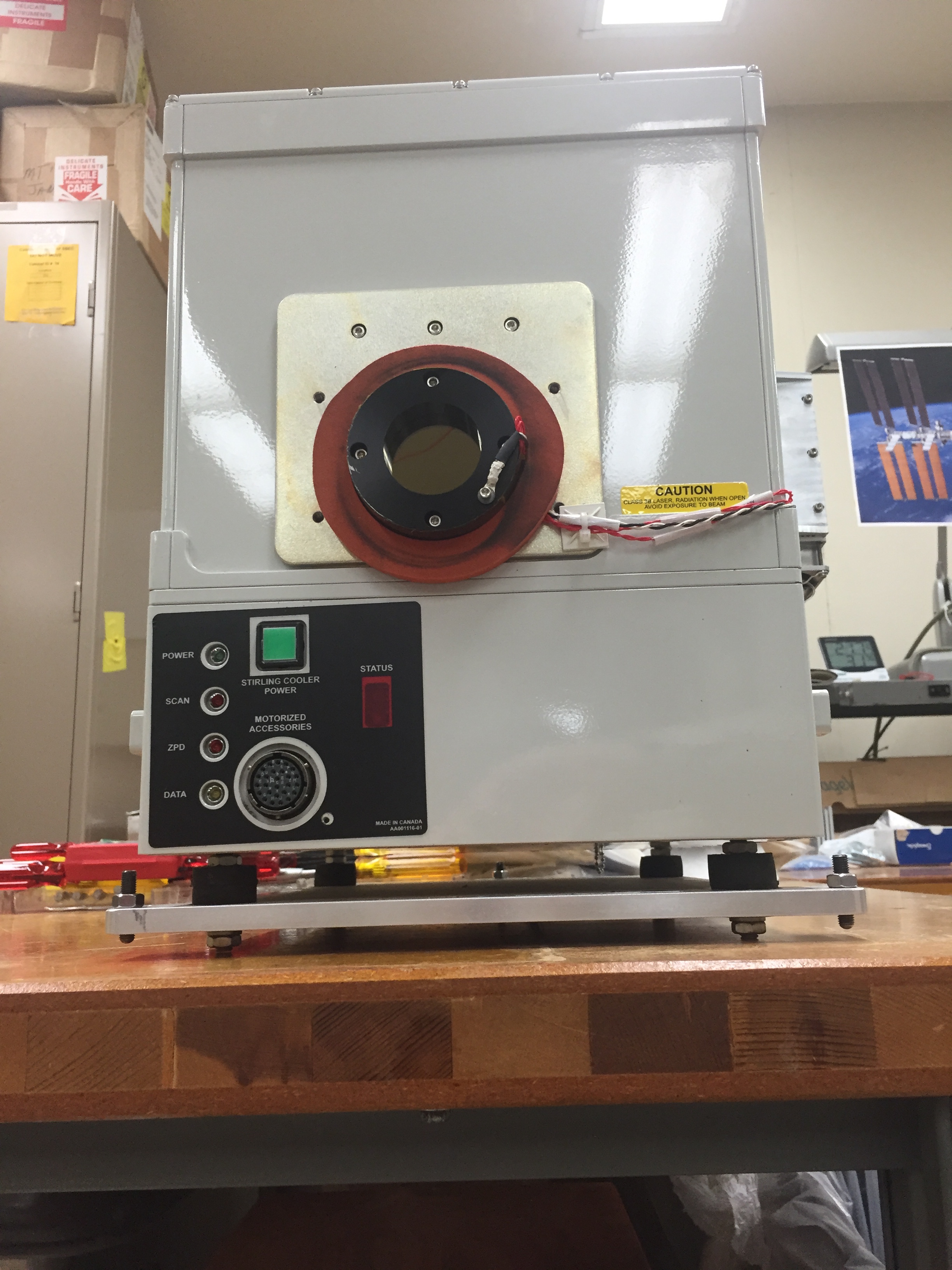
Figure 4. Removed MR unit, looking at the front window
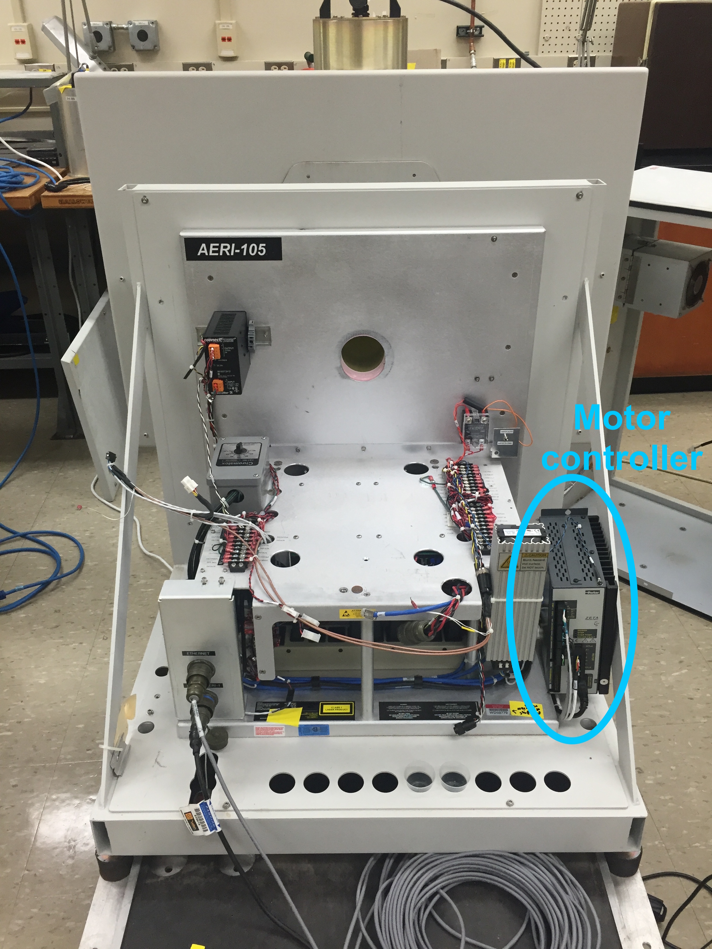
Figure 5. Back-end with MR unit removed. Note removed motor controller.