Pre-amplifier Replacement (MCT channel)
Tools and Equipment Required
- Anti-static wrist strap
- Hex driver set
- Phillips drivers
- 1/4″ wrench
- Replacement pre-amplifier board
Precaution
- The electronic boards are static sensitive. Always wear an anti-static wrist strap when handling electronic boards.
- A fragile tri-axial connector is used on the detector connector. Be sure not to apply any lateral forces when mating and de-mating this connector, to avoid damaging the fragile connector components.
- Keep the optics compartment clean!
- Be careful reaching into the interferometer from the top, wear gloves if necessary to prevent contamination of the optics
- Cover the top of the interferometer box when not actively working inside
- Look for and clean up any debris that may have fallen into the optics compartment
- Be attentive to not drop screws and washers in the optics compartment
Procedure
- Stop data collection and power OFF the instrument.
- Remove the top cover of the interferometer box (16x #4 hex screws, be sure not to loose washers) and store it in a clean location (see Fig. 1). Use all precautions necessary to keep the optics compartment clean, and do not touch any of the optics (mirrors).
- Using a 1/4″ wrench, carefully unscrew and de-mate the MCT detector connector from detector dewar (see Fig. 2). Be sure not to apply any lateral stress to the connector as it can damage the fragile tri-axial connector.
- Unscrew the 2x phillips screws holding the MCT ADC case to the MCT preamp case below (see Fig. 2).
- Carefully de-mate the ADC case from the preamp case below.
- Unscrew the 2x #10 hex screws holding the preamp case to the interferometer breadboard (see Fig. 3).
- Remove the preamp case. Note the path and orientation of the wires surrounding the case, so that they can be replaced in the same position.
- Cover / protect the interferometer compartment while the preamp board is being replaced.
- Replace the MCT preamp board (see Fig. 4).
- Take all precautions necessary to avoid static discharges when handling the preamp board: always wear and anit-static wrist strap, use an ESD mat if possible, and keep circuit boards in an anti-static bag when not in use.
- Open to top of the preamp case to reveal the board inside.
- Remove the old preamp board.
- Install the new preamp board.
- Carefully route the detector connector cable through the opening in the case.
- Replace the top of the preamp case.
- Replace the preamp case onto the interferometer breadboard using the 2x #10 hex screws.
- Re-mate the ADC case to the preamp case.
- Secure the ADC with the 2x phillips screws.
- Extremely carefully, re-mate the MCT detector connector to the detector dewar. Be sure not to apply any lateral stress to the connector as it can damage the fragile tri-axial connector. Use the 1/4″ wrench to tighten the connector. This will take some time as there is limited access to the screw.
- Be sure the top cover is clean, and replace the top cover of the interferometer box (16x #4 hex screws)
- Power ON the instrument and return to operation.
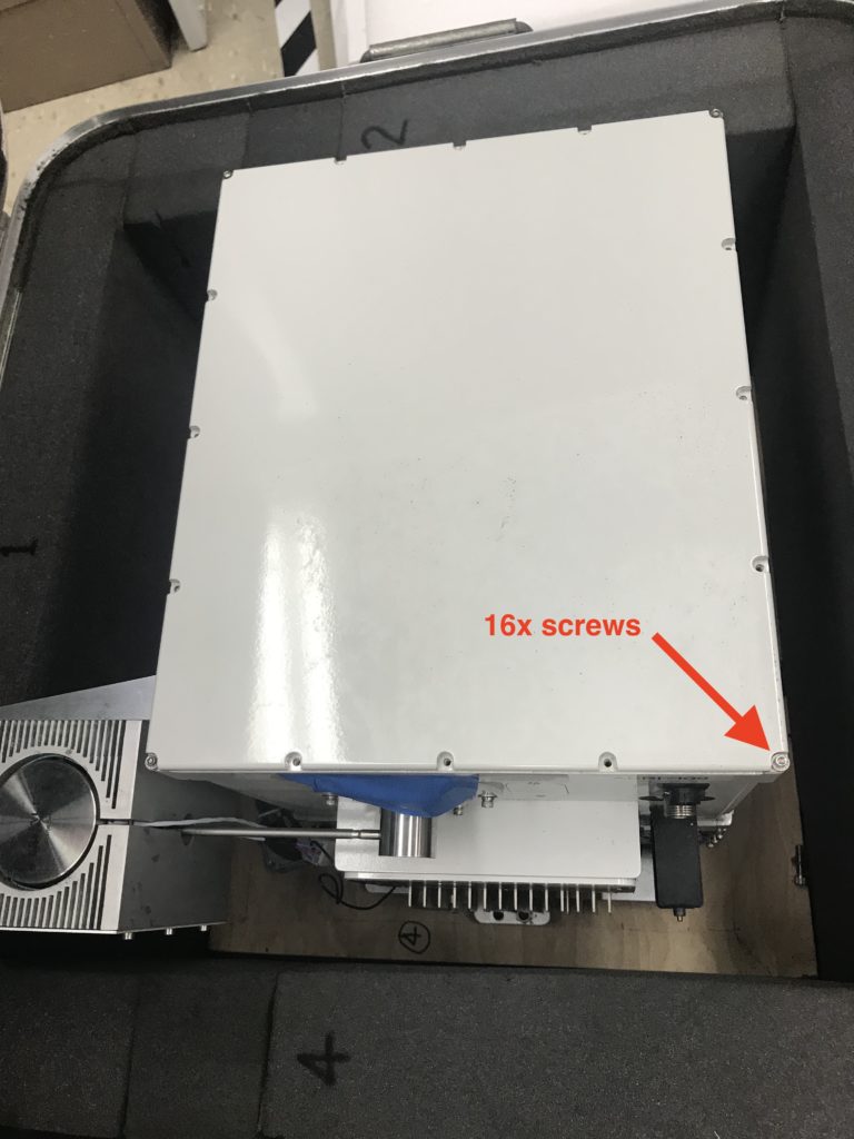
Figure 1. Top view of interferometer cover
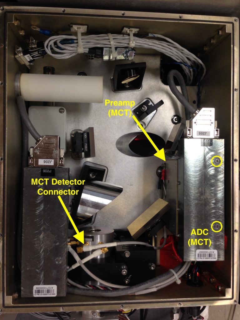
Figure 2. Top view of interferometer aft-optics compartment, showing the ADC (MCT), preamp (MCT) and detector dewar
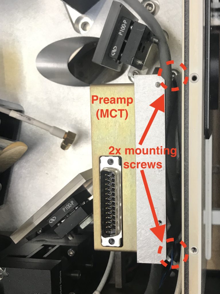
Figure 3. MCT preamp case, showing mounting screws
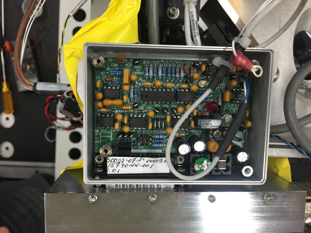
Figure 4. Preamp board