AERI 3rd Blackbody Calibration with Breakout Cable
Equipment Required
- Large flathead screwdriver
- Small phillips screwdriver
- Ball driver set
- 3rd Blackbody
- 3rd Blackbody breakout cable
Precaution
- Verify that the red aperture cover of the 3rd blackbody has been removed prior to installation
- Verify that the interior fan power cable is disconnected prior to running the test
- DO NOT power OFF the AERI instrument at any point during the test, as loss of power will automatically close the hatch and could potentially damage the hatch and 3rd blackbody
- Ensure that the ABB SP cable is disconnected after the test is complete
Procedure
Hardware setup
Inside:
- Stop data collection on the AERI
- Press ctrl-c up to 3 times in the black Cygwin window to terminate ingest, then close the FTSW window
- Set the front-end hatch to OPEN using the manual hatch control switch on the back right side of the back-end (Fig. 1)
- DO NOT power OFF the AERI instrument at any point during the test, as loss of power will automatically close the hatch and could potentially damage the hatch and 3rd blackbody
Outside:
- Remove the front-end front panel using the six flathead latches
- Disconnect the interior fan power cable (Fig. 2)
- Remove the sky view aperture plate (four #8 hex screws) (Fig. 3).
- Locate the 3rd blackbody and remove the red protective aperture cover (Fig. 4). Note the serial number of the 3rd blackbody (near handle) for software step #17 below.
- Install the 3rd blackbody onto the sky view port (in place of the sky view aperture plate) (Fig. 5)
- Secure the 3rd blackbody: 2 (of 4) screws in diagonal positions are enough – but do not tighten screws yet
- Push the 3rd blackbody flush against the optical alignment buttons (Fig. 3) on the back of the sky view port, so that it’s optically registered
- While pushing flush against the buttons, tighten the screws to secure the 3rd blackbody
- Connect the “3rd body” connector on the 3rd blackbody breakout cable to the 3rd blackbody (Fig. 5).
- Connect the remaining 2 connectors on the breakout cable (Fig. 6)
- Disconnect the ABB connector from the ABB extension cable (Fig. 2)
- Connect the ABB connector into “ABB Connector” on the breakout cable
- Connect the “ABB” connector on the breakout cable to the ABB extension cable
- Replace the front-end front panel to protect the front-end enclosure
Inside:
- Confirm that all three of the ABB controller cables are connected: ABB (white 10-pin), ABBC P (white 4-pin), ABBC SP (black 3-pin). These go to the blackbody controller board, on the AERI back-end near the power bar (Fig. 7). Note: the software configuration (below) should be done shortly after in order to prevent temperature runaway issues with the 3rd blackbody
Software setup
- Confirm AERI data collection (Ingest) has been stopped
- Manage the data directories
- Rename c:\ftp\AEYYMMDD, where YYMMDD is the current date (e.g. c:\ftp\AE210228)
- cd /cygdrive/c/ftp
- mv AEYYMMDD AEYYMMDDA
- Rename c:\AEYYMMDD, where YYMMDD is the current date (e.g. c:\AE210228)
- cd /cygdrive/c
- mv AEYYMMDD AEYYMMDDA
- Rename the contents of c:\temp, and create a new empty c:\temp directory
- cd /cygdrive/c
- mv temp tempA
- mkdir temp
- Delete c:\E-AERI\Data\EAERIHouseKeeping.hk, if it exists
- cd /cygdrive/c/E-AERI/Data
- rm EAERIHouseKeeping.hk
- Rename c:\ftp\AEYYMMDD, where YYMMDD is the current date (e.g. c:\ftp\AE210228)
- Change to 3rd body breakout configuration
- cd \\config
- change_config_to 3body_breakout
- cat mirror.beg (to verify new correct mirror program is selected, first line should read 6 1 for standard AERIs)
- Change FTSW configuration file
- Open the file c:\E-AERI\FTSW_EAERI.Config
- nano /cygdrive/c/E-AERI/FTSW_EAERI.Config
- Edit the file to set calibKitY.connected = true
- This should be near the bottom of the file
- Do not confuse with the similar line calibKit.connected
- Save the file
- Open the file c:\E-AERI\FTSW_EAERI.Config
- Run FTSW_EAERI_GUI.bat (click FTSW on the desktop)
- The software detects modification of the configuration file (see Fig. 8). Click OK to start FTSW in calibration mode
- Select the blackbody coefficient file for the 3rd blackbody
- This is typically in the path c:\3rd_BB_coeffs
- Use the file for the serial number of the 3rd blackbody, from step 7 above
- Verify that ref1 Blackbody is displayed in FTSW and heating and stabilized at the correct temperature (Fig. 9)
- The default setting is 45°C, and the blackbody heats at a rate of ~1°C/min
- Exit FTSW
Running the test
- Run Ingest.bat to start the 3rd blackbody test (click Ingest on the desktop)
- Run the test for 0.5 – 1.5 hours, until a sufficient number of records have been collected
- The first record appears approx. 14 mins after Ingest starts, the next ones approx. 7 mins after
- The results can be analyzed using the cal_val module in AERI ARMORY. The two .RNC files are needed as input
- To terminate the test, press ctrl-c up to 3 times in the black Cygwin window, and close the FTSW window
Software packup
- Manage the data directories
- Rename c:\ftp\AEYYMMDD, where YYMMDD is the current date (e.g. c:\AE210228)
- cd /cygdrive/c/ftp
- mv AEYYMMDD AEYYMMDD_3body
- If it is desired to resume ingest on the current UTC day and append to the previous sky data
- mv AEYYMMDDA AEYYMMDD
- Rename c:\AEYYMMDD, where YYMMDD is the current date (e.g. c:\AE210228)
- cd /cygdrive/c
- mv AEYYMMDD AEYYMMDD_3body
- If it is desired to resume ingest on the current UTC day and append to the previous sky data
- mv AEYYMMDDA AEYYMMDD
- If data is not being appended to the current UTC day, then delete the contents of c:\temp, carefully double-check the correct path to avoid accidentally deleting something else
- cd /cygdrive/c/temp
- rm *
- Else, if it is desired to resume ingest on the current UTC day and append to the previous sky data
- cd /cygdrive/c
- rm -r temp
- mv tempA temp
- Delete c:\E-AERI\Data\EAERIHouseKeeping.hk
- cd /cygdrive/c/E-AERI/Data
- rm EAERIHouseKeeping.hk
- Rename c:\ftp\AEYYMMDD, where YYMMDD is the current date (e.g. c:\AE210228)
- Change to normal science configuration
- cd \\config
- change_config_to RS_3
- cat mirror.beg (to verify new correct mirror program is selected, first line should read 20 1 for standard AERIs)
- Change FTSW configuration file
- Open the file c:\E-AERI\FTSW_EAERI.Config
- nano /cygdrive/c/E-AERI/FTSW_EAERI.Config
- Edit the file to set calibKitY.connected = false
- This should be near the bottom of the file
- Do not confuse with the similar line calibKit.connected
- Save the file
- Open the file c:\E-AERI\FTSW_EAERI.Config
- Run FTSW_EAERI_GUI.bat in order to reset the blackbodies to normal operation. Verify that ambientBlackbodyTop, ambientBlackbodyApex, ambientBlackbodyBottom are all displayed. Close FTSW. This step is critical to prevent the Ambient Blackbody from heating up in step 27
- Send the directory c:\ftp\AEYYMMDD_3body to the mentor team for analysis
Hardware packup
Inside:
- Disconnect the ABBC SP cable from the ABB blackbody controller board connector on the AERI back-end (Fig. 7). At sites that experience cold winter temperatures, also disconnect the ABBC P (white 4-pin) cable, to prevent the ABB from bias heating in the winter
Outside:
- Remove the front-end front panel
- Disconnect the 3rd blackbody breakout cable
- Reconnect the ABB connector to the ABB extension cable (Fig. 2)
- Uninstall the 3rd blackbody
- Replace the red protective aperture cover (Fig. 4)
- Re-install the sky view aperture plate (Fig. 3)
- Secure the aperture plate using the four #8 hex screws – but do not tighten screws yet
- Push the aperture plate flush against the optical alignment buttons on the back of the sky view port, so that it’s optically registered
- While pushing flush against the buttons, tighten the screws to secure the aperture plate
- Re-connect the interior fan power cable (Fig. 2)
- Re-install the front-end front panel using the six flathead latches
Inside:
- Set the front-end hatch back to AUTO using the manual hatch control switch (Fig. 1)
- Re-start data collection (run Ingest.bat) and return the instrument to service
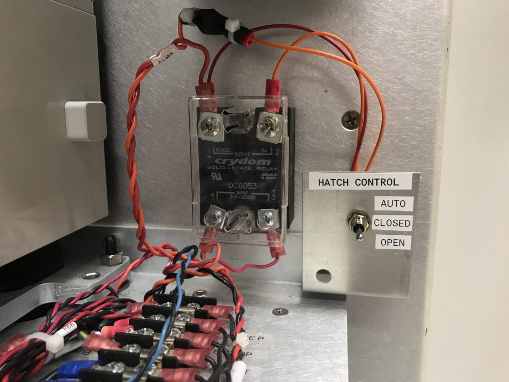
Figure 1. Hatch control switch
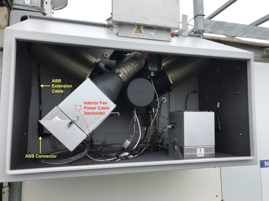
Figure 2. AERI front-end enclosure wiring
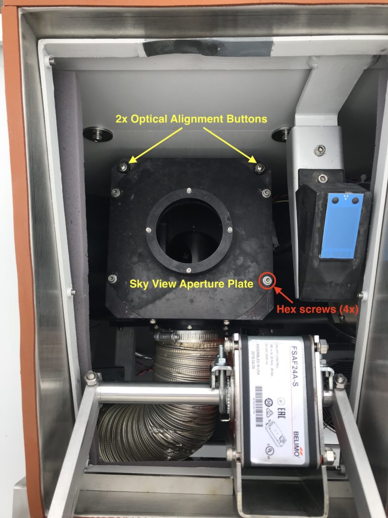
Figure 3. AERI sky view aperture
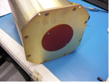
Figure 4. 3rd blackbody with red aperture cover
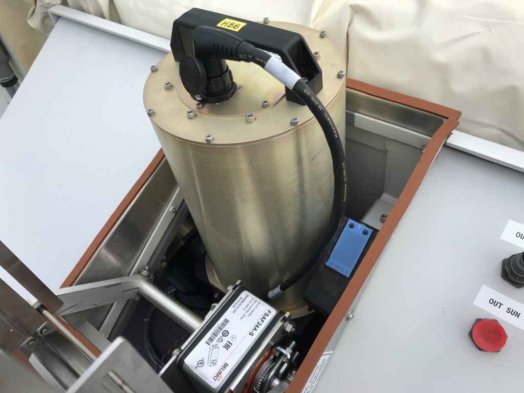
Figure 5. 3rd blackbody installed through the front-end hatch
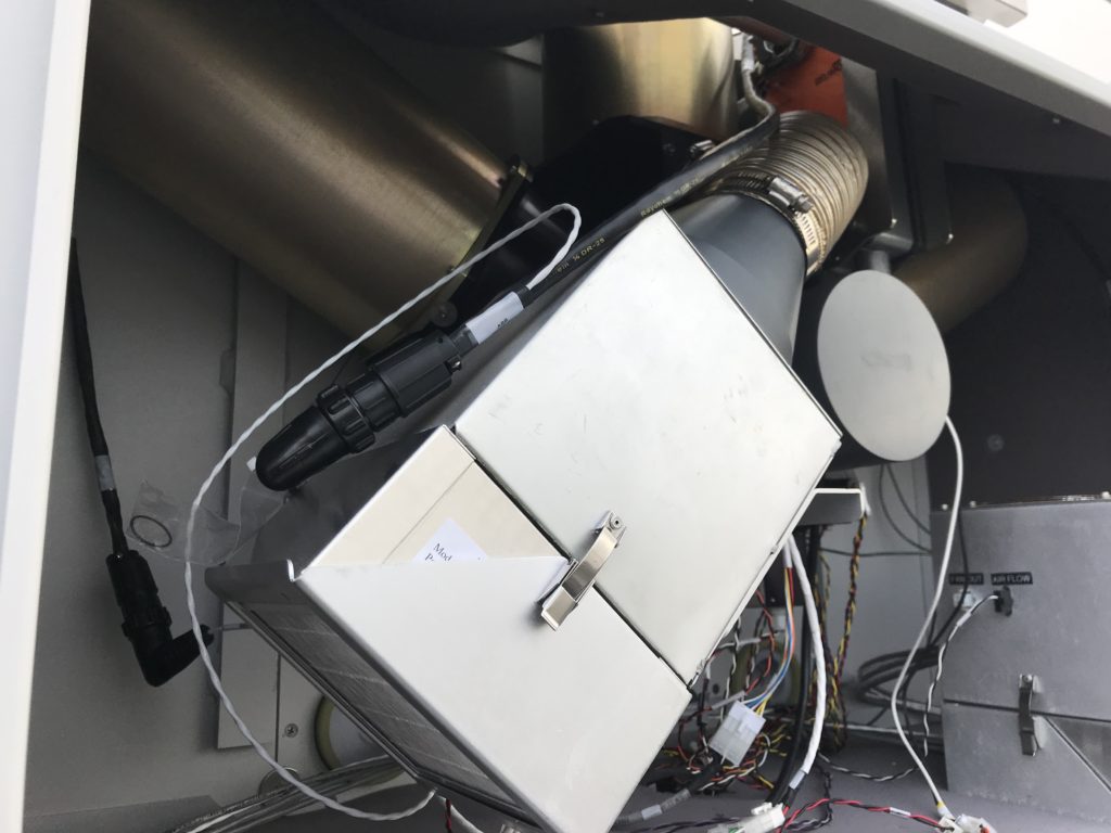
Figure 6. 3rd blackbody breakout cable wiring configuration
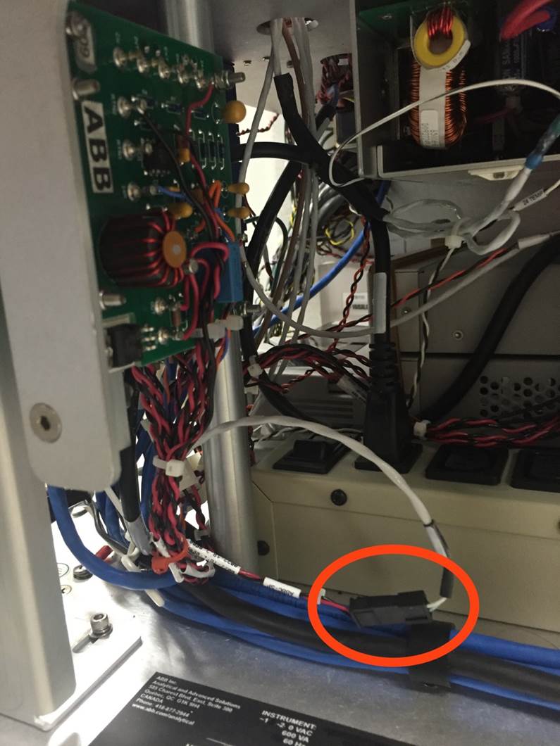
Figure 7. ABBC SP connector on the AERI back-end
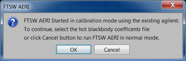
Figure 8. FTSW startup detects a configuration change
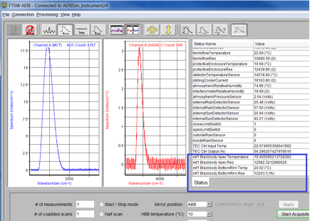
Figure 9. FTSW housekeeping panel showing 3rd blackbody temperature readings (ref1)