AERI Profiling Module Installation
Tools needed
- Ladder
- Large flathead screwdriver
- Hex driver set
- Wrenches
- Drill & 3/8″ bit
A. Container
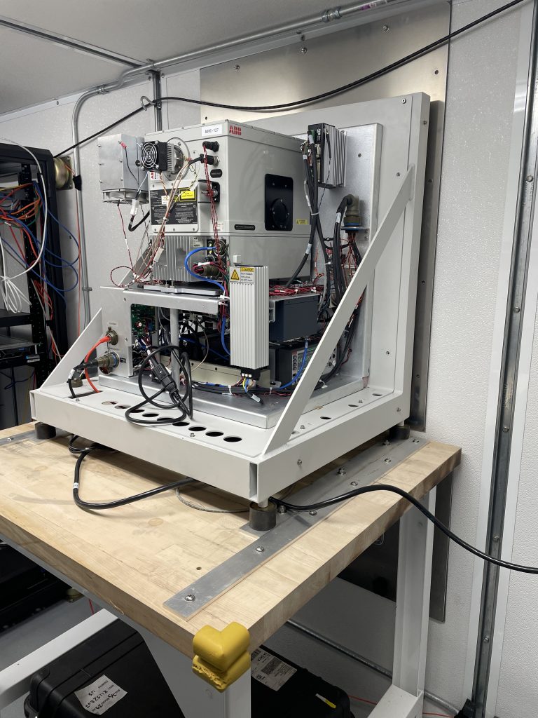
- Inspect the AERI back-end and confirm there is no damage to the instrument and wiring
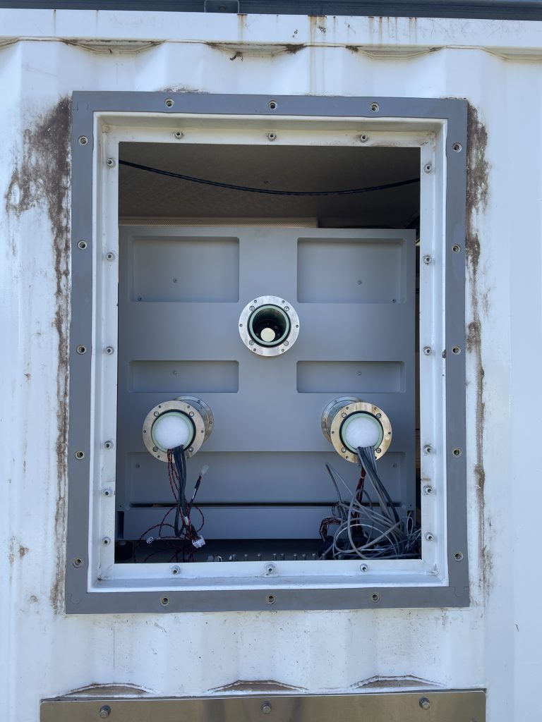
- Remove the blank shipping cover for the AERI port. Note that the smaller port below is no longer used (old V2 AERI blower port), so the blank cover should stay on that
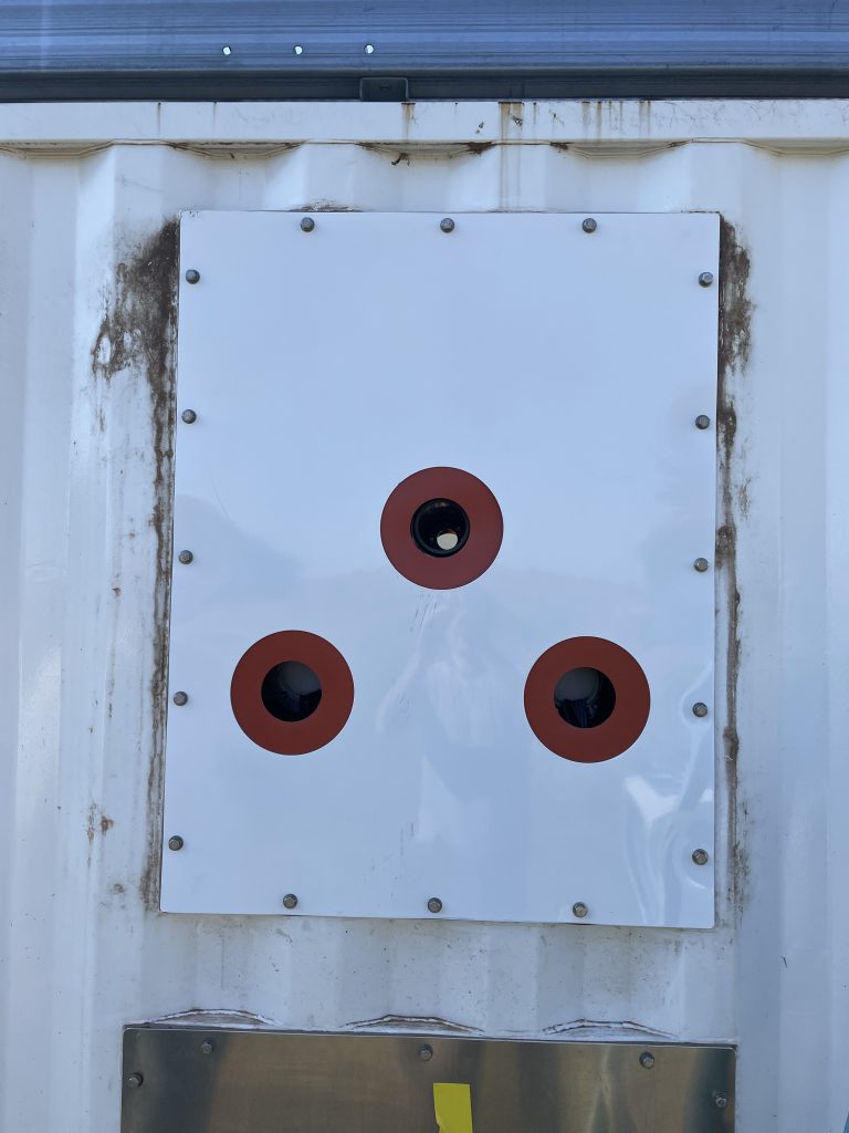
- Install the AERI exterior plate (with the 3 large holes) with the rubber gasket behind it. Confirm the gasket is sound with no tears around the 3 large holes – replace the gasket with a spare if necessary
B. Back-end
- For the E41 site only: the two thru-holes for the AERI feet rails closest to the container wall still need to get drilled. This can be done during the installation process while it’s easily accessible. ~3/8″ bit works well
- Remove the bolts securing the AERI rail to the table, so that the AERI can slide
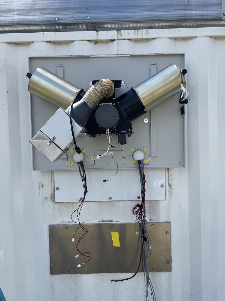
- Bring all the wiring from the AERI tubes outside through the rubber gasket and plate. Be careful not to damage any of the wiring, especially along the metal edges
- Slide the AERI forward to bring the tubes fully outside the container. The tubes may need help to get pushed through the rubber
- Line up the rails with the thru-holes in the table for the ‘deployed’ position and replace the 6x bolts to secure the instrument on to the table
- Install the iBootBar and cables (from the black accessories case): Mil-spec power cable from AERI to iBootBar; iBootBar power to UPS outlet; Ethernet from AERI to server; Ethernet from iBootBar to server
- Do NOT power ON the instrument yet
C. Front-end
- Install the trapezoidal bulkhead plate: screw in the 18x hex screws. IMPORTANT: use a straight hex driver (not balled!) because a balled driver could strip the shallow hex screws
- Install the front-end backplate: screw in the 8x 1/4″ hex screws + fender washers
- Install the black trapezoidal ‘hex’: screw in the 4x nuts. Confirm that the hex is optically registered to the 3 alignment buttons at the bottom and right before tightening. The wires going to the hex can be connected at this point
- Install the two {blackbody + black extension tube + 1.5′ extension cable} assemblies, with the blackbody connector on top: screw in 4x #8 hex screws for each. Remove the aperture cover or any tape over the aperture (covers can be stored in the black accessories case). Confirm that the black extension tube is optically registered to the 2 alignment buttons below before tightening. The blackbody cables from the AERI can be connected to the 1.5′ extension cables at this point
- Install the hex fan assembly: screw in the 4x #8 hex screws under the hex, then slide the silver tubing over the input port on the hex and tighten the hose clamp. The FAN IN connector can be connected to the back of the fan assembly at this point since it’s easily accessible
- Install the front-end enclosure: carefully lift up and around the blackbodies, and ensure none of the cables get pinched at either sides or bottom of the enclosure; screw in the 5x #10 hex screws
- Connect all remaining cables between the AERI and the front-end
- Install the front panel
- Power ON the AERI


