New Front-end Field Installation
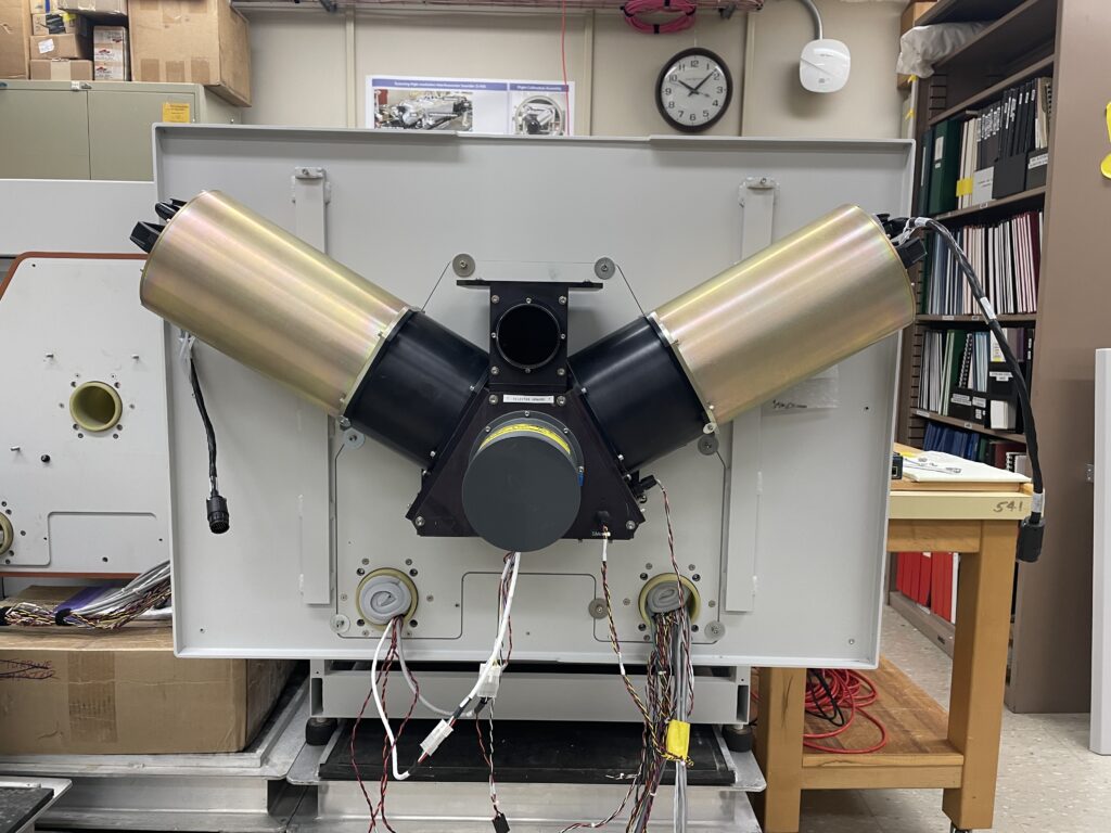
New front-end components
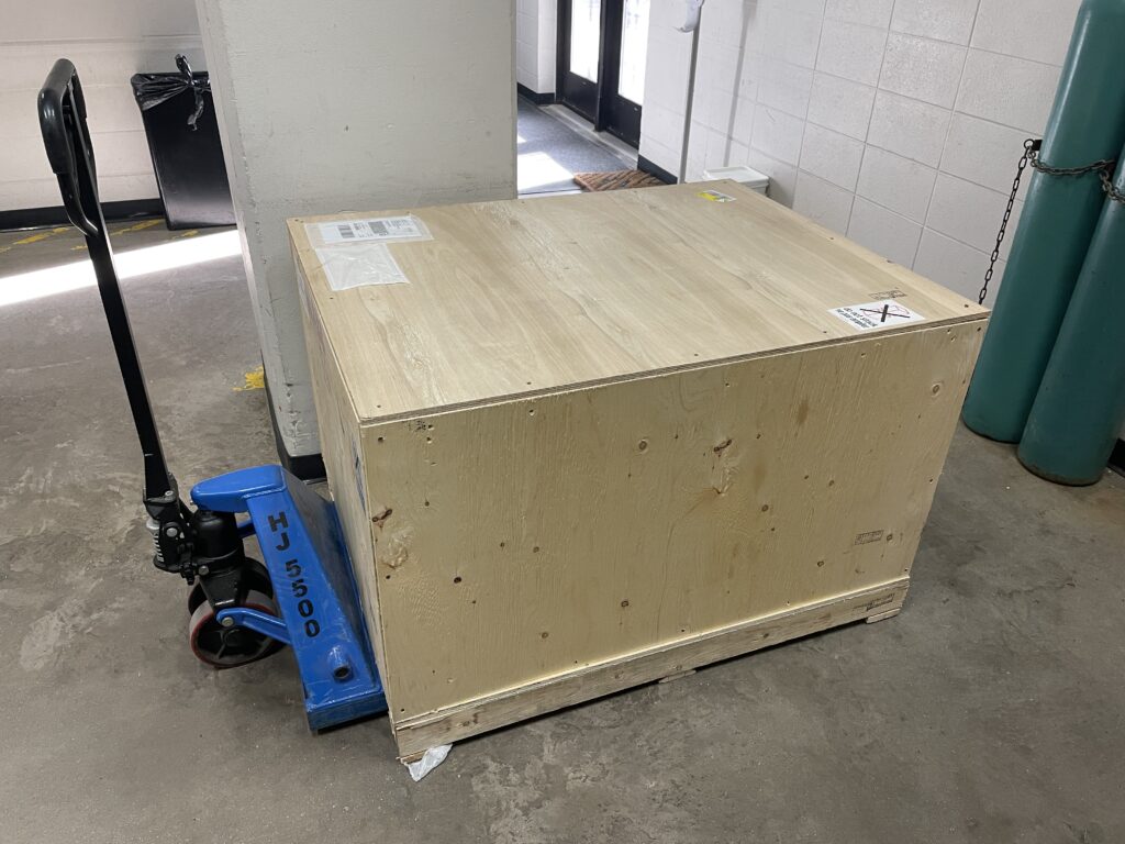
The new front-end will arrive in a wooden crate. Only the top of the crate needs to be removed to access the front-end.
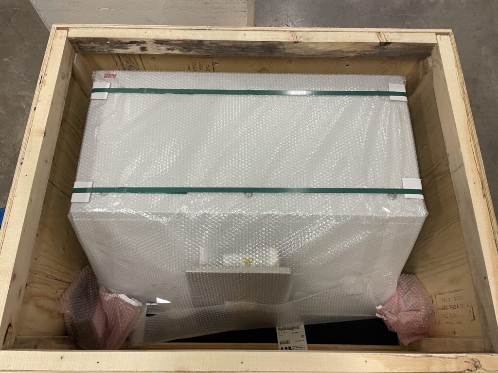
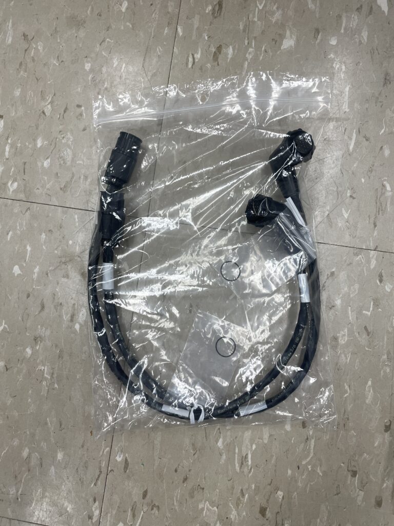
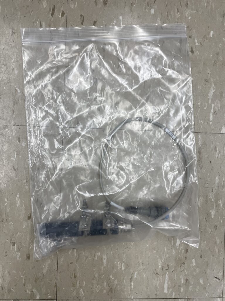
Inside the new front-end are a pair of blackbody extension cables, and the sun sensor.
Removing the existing front-end
First, the hatch assembly on the old front-end must be unscrewed. It’s important to do this first, because the mounting screws can only be accessed with the hatch open, and this is much easier to do with the old front-end still attached to the AERI
- Stop AERI Ingest. Keep the AERI powered ON.
- Using the manual hatch switch on the AERI back-end, set the hatch to OPEN
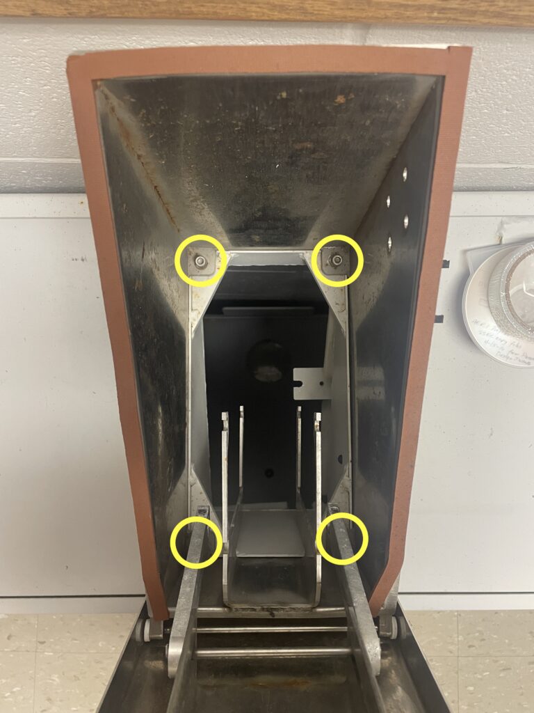
- Looking down through the hatch, unscrew the four 1/4″ hex screws that attach the hatch assembly to the enclosure. Remove the screws (they can be tossed). The hatch assembly can stay in place until the shipping steps at the end
- Set the manual hatch switch back to AUTO
Next, follow all steps in the AERI Front-end Enclosure Removal Procedure to remove the front panel, cables, and enclosure. Note: there is no need to remove the interior fan power cable (FAN IN) in Step #3
Then, disconnect the two blackbody cables, and remove the two blackbodies. Note: there’s no need to remove the interior fan assembly and duct.
Unscrew the eight 1/4″ hex screws with the fender washers, and remove the back-plate
Configuration and Installation of the new front-end
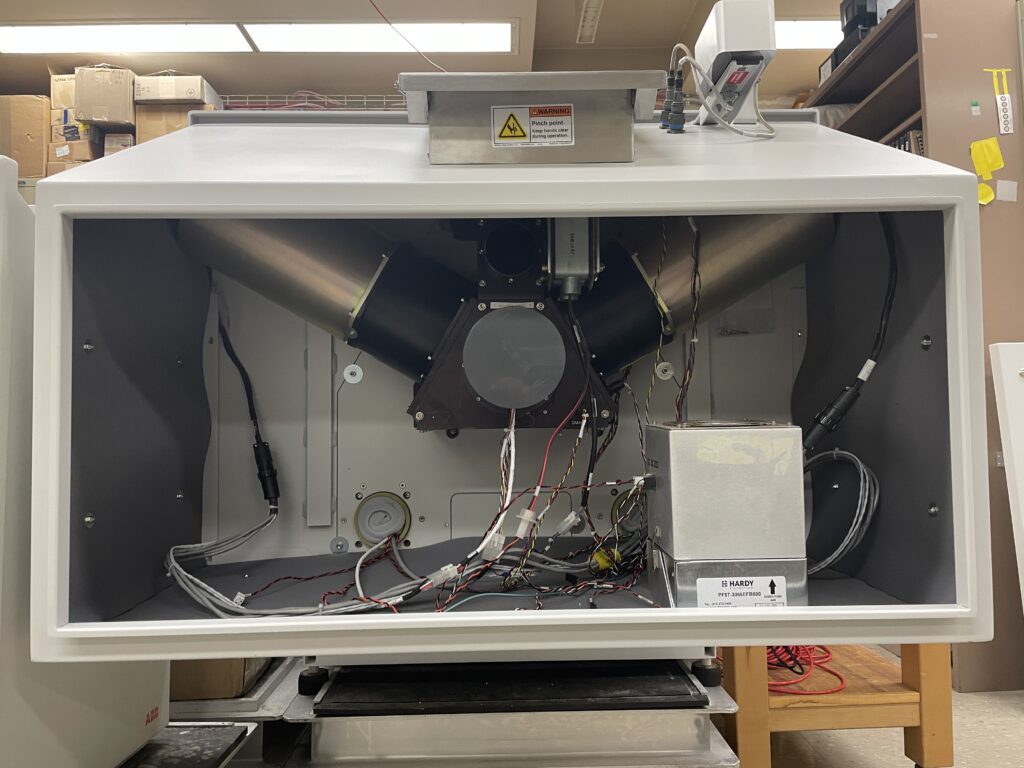
Remove the front panel of the new front-end using a large flat-head driver on the six latches.
Unscrew the five #10 hex screws inside the enclosure to remove the back-plate of the new front-end.
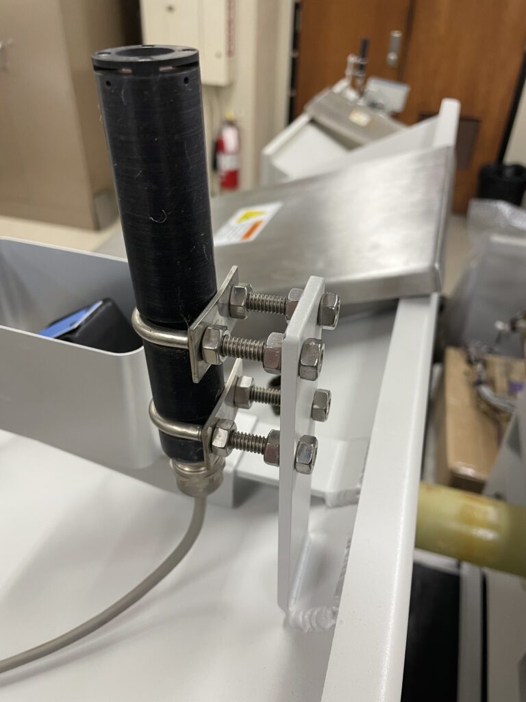
Install the sun sensor, shipped in the bag inside the front-end, onto the new front-end enclosure, and mate the amphenol connector
Install the new back-plate onto the AERI using the existing eight 1/4″ hex screws and fender washers

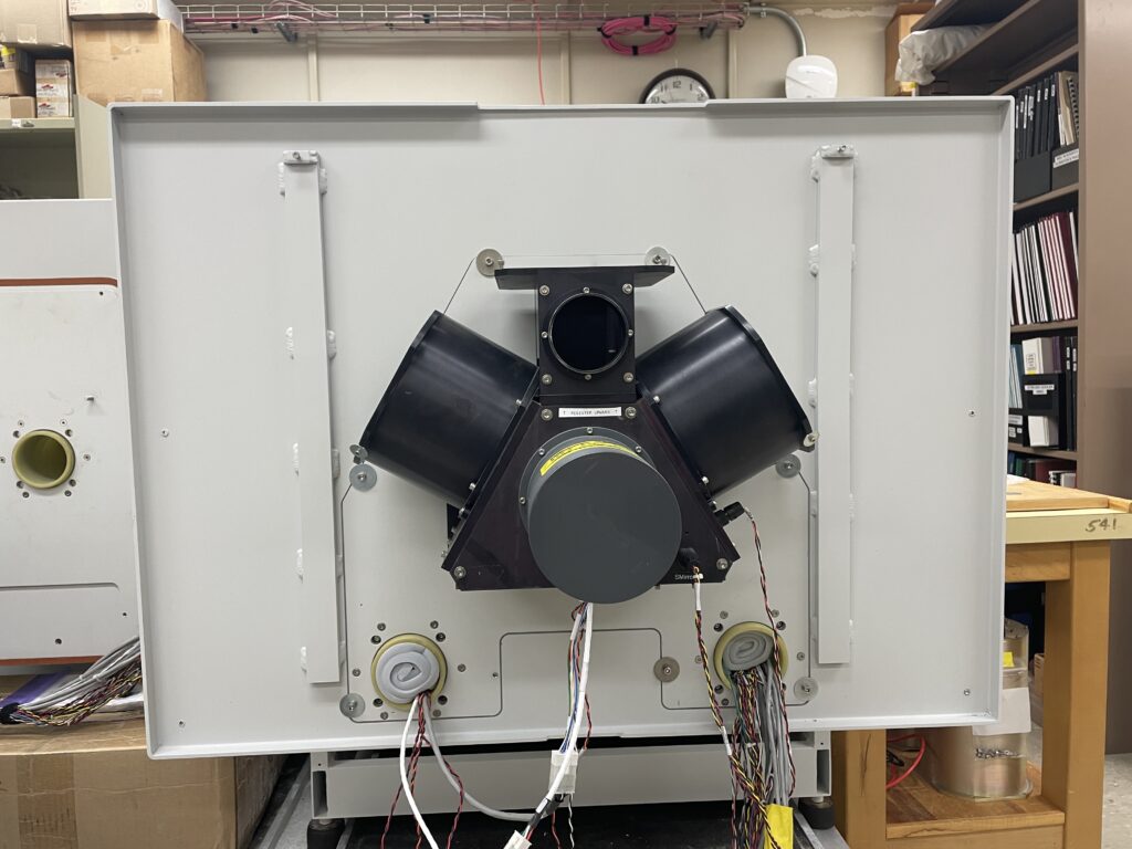
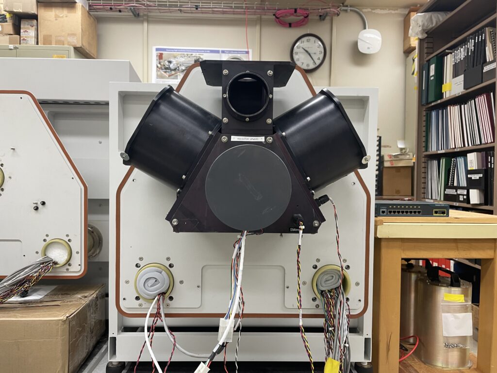
Install the two blackbodies, and connect the two 1.5 ft extension cables. Confirm that the ABB & HBB are on the correct sides. Note: the blackbodies need to be installed with the connector on top, to provide clearance for the cables.
Follow all steps in the AERI Front-end Enclosure Installation Procedure to install the enclosure, cables, and front panel.
- For Step #2, connect the existing blackbody cables to the 1.5 ft extension cables
- For Step #3, the interior fan power cable (FAN IN) should already be attached if it wasn’t disconnected earlier
- For Step #5, be sure to use the new set of five #10 screws that came with the new front-end. These are brand new screws and have some anti-seize on them
- For Step #7, the new panel will have six latches that are secured using a large flat-head driver
Return shipping of the old front-end
Remove the hatch assembly from the old enclosure. If this was unscrewed earlier, then the assembly can just be lifted straight up and out. Wrap the assembly in some packing material, and place it inside the old enclosure.
Install the old back-plate onto the old enclosure using the old five #10 screws.
Install the old front panel onto the old enclosure using the captive screws, or use tape if necessary.
Pack the old enclosure into the shipping crate and ship back to UW-SSEC.