AERI Scene Mirror Replacement Procedure
Tools and Equipment Required
- Replacement mirror (Laser Beam Products p/n SNICU100-12-00)
- Large phillips screwdriver
- Ball driver set
- Soft wipes
- (Optional) Holding fixture for the scene mirror assembly
- (Optional) Tweezers for holding mirror screws
Precaution
- The motor cables must NEVER be disconnected with the motor controller powered, as it can damage the stepper motor. Always power off the motor controller or instrument first.
- Be careful if handling the drum around the scene mirror: it is thin and easily bent.
- Do not touch the mirror surface. Wear gloves or use soft wipes when handling optics.
- There are four springs that will come loose when the mirror is removed: be sure to collect them.
- There may be thermal grease used between the back of the mirror and the heater plate: avoid contaminating any other surfaces with thermal grease.
- The mirror assembly must be registered upward upon replacement for proper optical alignment.
Procedure
- Stop data collection and power off the instrument:
- Press ctrl-c up to 3 times in the black Cygwin window to terminate ingest.
- Switch off the power bar in the AERI back-end
- Remove the front panel from the AERI front-end.
- Remove the scene mirror/motor assembly from the front end structure:
-
- The interior fan may obstruct removal of the assembly. In this case the fan assembly can be slightly rotated by removing the 3 front screws holding it to the hex. Alternatively the entire fan assembly can be removed.
- Disconnect the 4 cables going to the trapezoidal plate (ensure that motor controller is powered off):
- ENCODER
- MOTOR
- MO TEMP / PE TEMP
- S MIRROR
- Unscrew the 4 screws on the trapezoidal plate (see Fig. 1).
- Pull the assembly carefully straight out of the support structure (see Fig. 2).
- Place the assembly carefully onto a flat surface, or place it onto a holding fixture (see Fig. 3).
- Inspect the area inside the hex (from where the mirror assembly was removed); note and clean any debris or obstructions (grass, dirt, nests, etc.). Inspect the mirror drum for obstructions and circularity. Note the condition of the mirror surface before replacement.
- Remove the old mirror:
- Remove the 4 screws and 8 washers that retain the mirror (see Fig. 4). A 7/64” ball driver is required as the driver will be slightly tilted when it is being used through the drum aperture. Note: avoid having the screws drop across the mirror surface and possibly scratch it.
- Carefully remove the mirror (see Fig. 5). The drum can be rotated so that the mirror drops out. Note: Wear gloves or use soft wipes when handling optics. Note: There are four springs providing pressure behind the mirror that will be loose when the mirror is removed: be sure to collect them (see Fig. 6).
- Remove the heater plate from the back of the mirror. There may be thermal grease holding this plate to the back of the mirror. Note: Avoid contaminating any other surfaces, especially the front of the mirror, with thermal grease.
- Carefully package the old mirror by avoiding contact/pressure on the front optical surface. Notify UW-SSEC and return the mirror to SGP for refurbishment.
- Install the new mirror:
- Ensure that the heating plate and the 4 springs are in proper position (see Fig. 6).
- Install the new mirror into position (see Fig. 5). Note: Wear gloves or use soft wipes when handling optics.
- Reinstall the 4 screws and 8 washers that retain the mirror (see Fig. 4). Only the nylon washers should be in contact with the mirror surface. Note: Avoid touching or scratching the mirror with the screws.
- Reinstall the mirror/motor assembly:
- Carefully insert the assembly straight into the support structure (see Fig. 2).
- Register the front plate upward when tightening the four socket head screws.
- Reconnect the 4 cables going to the trapezoidal plate.
- Return the interior fan assembly to it’s original position, if it was moved.
- Rotate the mirror/drum assembly by hand through its full range (250°) and check for any interference of the drum with the two baffles on the structure. (Removing the bottom plate hole cover allows access for hand rotation. Replace cover when done.)
- Reinstall the front panel onto the AERI front-end.
- Power on the instrument and resume data collection:
- Switch on the power bar in the AERI back-end
- Click ingest.bat on the desktop to begin ingest.
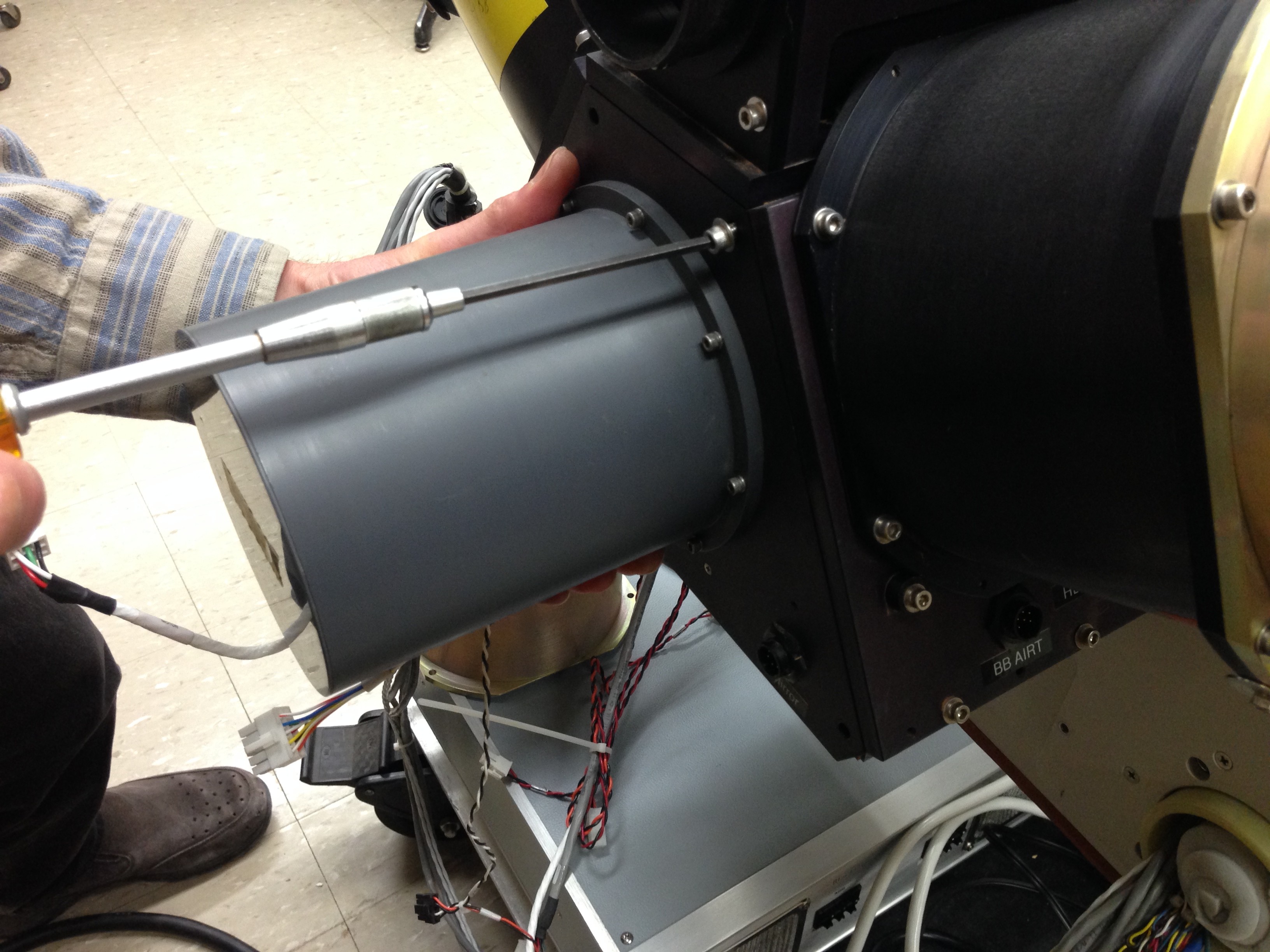
Figure 1. Unscrewing the mirror/motor assembly
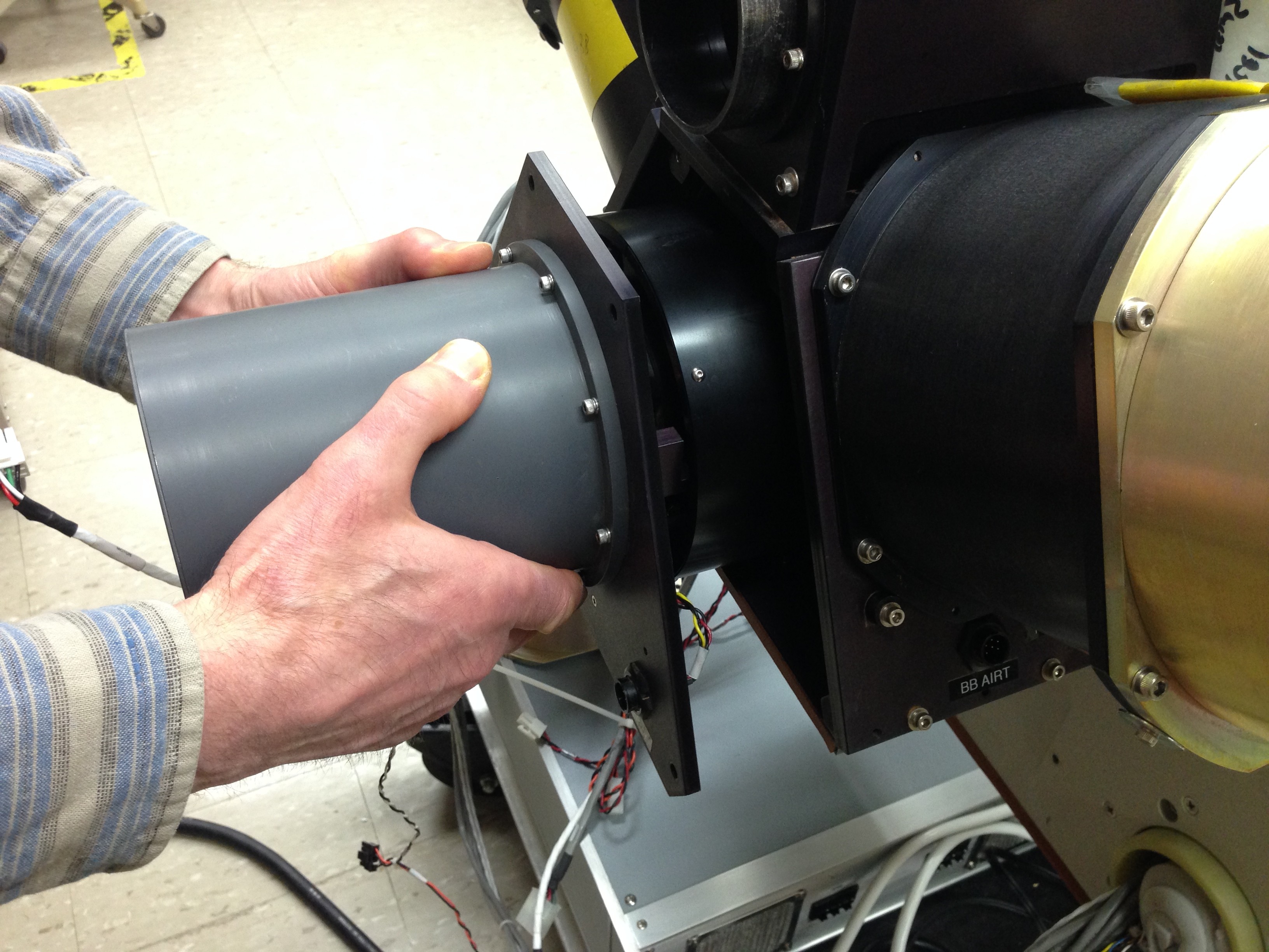
Figure 2. Mirror motor assembly removal or insertion
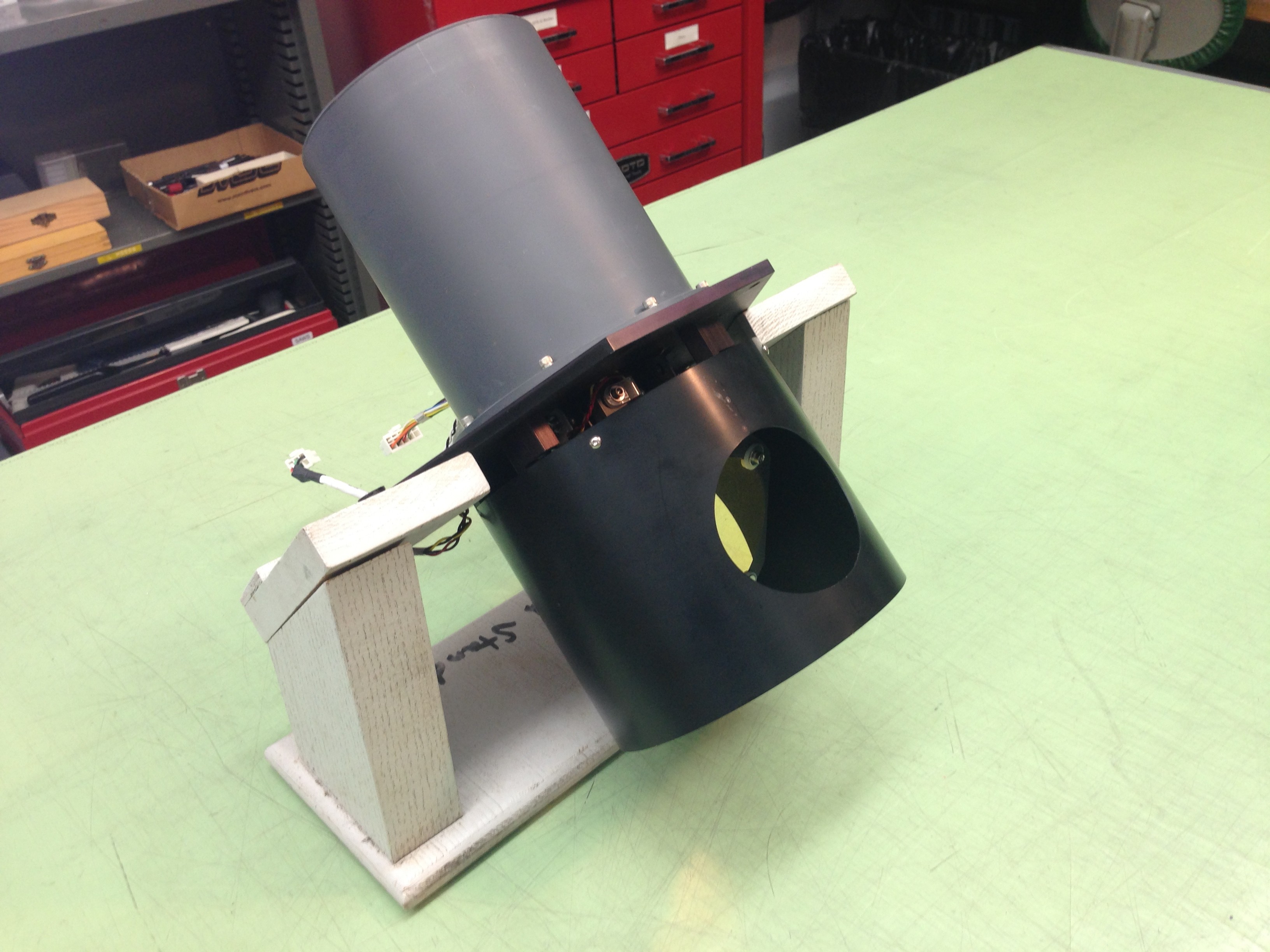
Figure 3. Removed mirror/motor assembly on holding fixture
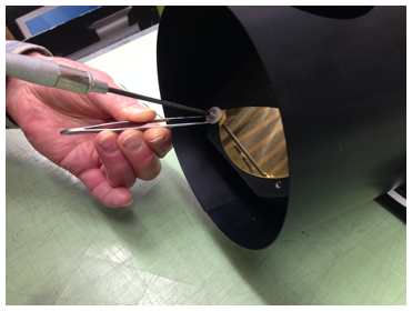
Figure 4. Four sets of screws and washers retain the mirror
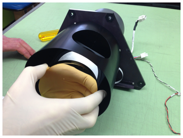
Figure 5. Mirror removal/installation
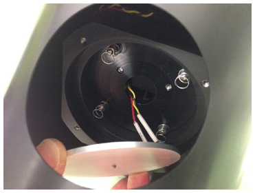
Figure 6. Four springs retaining the mirror