M-AERI Scene Mirror Replacement Procedure
Tools and Equipment Required
- Replacement mirror (Laser Beam Products p/n SNICU100-12-00)
- Large flathead screwdriver
- Ball driver set
- Soft wipes
- Gloves
- (Optional) Tweezers for holding mirror screws
Precaution
- The motor cables must NEVER be disconnected with the motor controller powered, as it can damage the stepper motor. Always power off the motor controller or instrument first.
- Do not touch the mirror surface. Wear gloves or use soft wipes when handling optics.
- There are four springs that will come loose when the mirror is removed: be sure to not lose them.
Procedure
- Stop data collection:
- In the black cygwin window, press <ctrl>+c multiple times
- Close the cygwin windows
- Close the FTSW window
- Ensure that all windows are closed and that ingest has been fully terminated
- Power OFF the instrument
- Open the M-AERI back-end
- Power OFF the instrument using the switch on the power bar inside the instrument
- Confirm the instrument is OFF, lights no longer flashing
- Remove the front panel from the M-AERI front-end.
- Remove the scene mirror/motor assembly from the front end structure:
-
- Disconnect the 2 milspec connectors going to the mirror motor (1J13, 1J14) (see Fig. 1).
- Unscrew the 4 (#8 socket head) screws on the circular plate (see Fig. 2).
- Pull the assembly carefully straight out of the support structure.
- Note the orientation of the drum and mirror – they must be co-aligned when replacing the mirror assembly. The easiest position for replacing the mirror is with the mirror pointing up: if necessary, rotate the drum so that the two cutouts are horizontal (see Fig. 3) and the aperture in the drum is at the top.
- Place the assembly carefully onto a flat surface (see Fig. 4).
- Inspect the area inside the hex (from where the mirror assembly was removed); note and clean any debris or obstructions.
- Remove the old mirror:
- Inspect the two nylon screws on the sides of the mirror assembly (see Fig. 4) and tighten if necessary.
- Note the condition of the mirror surface before replacement.
- Remove the 4 screws and 8 washers that retain the mirror. Note: carefully avoid having the screws drop across the mirror surface and possibly scratch it.
- Carefully remove the mirror. The drum can be rotated so that the mirror drops out. Note: Wear gloves or use soft wipes when handling optics. Note: There are four springs providing pressure behind the mirror that will be loose when the mirror is removed: be sure to collect them (see Fig. 6).
- Carefully package the old mirror by avoiding contact/pressure on the front optical surface. Return for refurbishment.
- Install the new mirror:
- Ensure that the 4 springs are in proper position (see Fig. 5).
- Install the new mirror into position (see Fig. 6). Note: Wear gloves or use soft wipes when handling optics.
- Reinstall the 4 screws and 8 washers that retain the mirror (see Fig. 4). Only the nylon washers should be in contact with the mirror surface. Note: Avoid touching or scratching the mirror with the screws. (Optional) Use tweezers to hold the screws for stability.
- Reinstall the mirror assembly:
- Verify that the two cutouts on the drum for the nylon screws are horizontal and that the scene aperture in the drum is at the top (see Fig. 3).
- Carefully insert the mirror assembly straight into the hex, with the nylon screws horizontal and the mirror pointing up.
- Register the nylon screws in the cutouts in the drum.
- Re-install the 4 (#8 socket head) screws on the circular plate (see Fig. 2).
- Reconnect the 2 milspec connectors going to the mirror motor (1J13, 1J14) (see Fig. 1).
- Double-check that the mirror is facing towards open aperture in the drum.
- Reinstall the front panel onto the M-AERI front-end.
- Power on the instrument and resume data collection
-
- Turn ON the M-AERI with the power bar inside the back-end
- Click ingest.bat on the desktop to begin ingest.
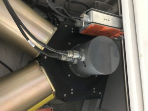
Figure 1. M-AERI scene mirror assembly
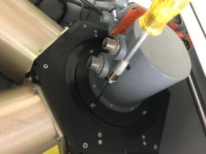
Figure 2. 4 socket head screws hold the scene mirror assembly
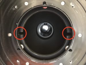
Figure 3. Mirror drum should be turned so that cutouts are horizontal, and the drum aperture is at the topshould be horizontalRemoved mirror/motor assembly on holding fixture
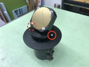
Figure 4. M-AERI scene mirror assembly, with nylon screws indicated.
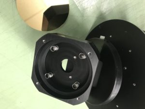
Figure 5. Four springs retaining the mirror
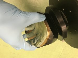
Figure 6. Mirror installation
