ADC Board Replacement
Tools and Equipment Required
- Hex driver set
- Phillips drivers
- Replacement ADC boards
Precaution
- The electronic boards are static sensitive. Always wear an anti-static wrist strap when handling electronic boards.
- Keep the optics compartment clean!
- Be careful reaching into the interferometer from the top, wear gloves if necessary to prevent contamination of the optics
- Cover the top of the interferometer box when not actively working inside
- Look for and clean up any debris that may have fallen into the optics compartment
- Be attentive to not drop screws and washers in the optics compartment
Procedure
- Stop data collection and power OFF the instrument.
- Remove the top cover of the interferometer box (16x hex screws). Use all precautions necessary to keep the optics compartment clean, and do not touch any of the optics (mirrors).
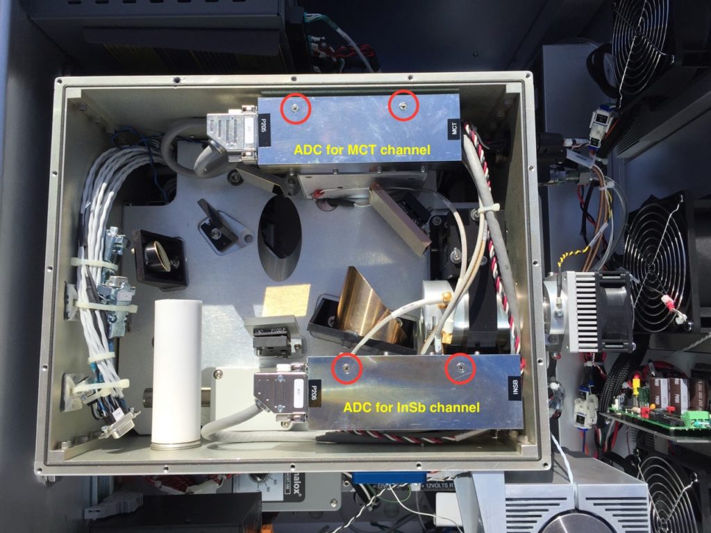
- Disconnect the ADC harness using the thumb screws (P205 for MCT Channel 1; P206 for InSb Channel 2).
- Unscrew the 2x phillips screws holding the ADC case to the interferometer box structure (see Fig. 1).
- Carefully de-mate the ADC case from the preamp case below.
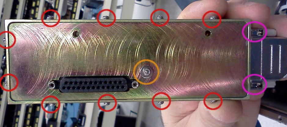
- Open the ADC case by unscrewing all of the necessary screws (see Fig. 2).
- Remove the ADC board. Be sure to avoid static discharges by wearing an anti-static wrist strap.
- Install the replacement ADC board.
- Close the ADC case by replacing all the necessary screws (see Fig. 2).
- Carefully re-mate the ADC case to the preamp case.
- Attach the ADC case to the interferometer box structure using the 2x phillips screws (see Fig. 1).
- Reconnect the ADC harness and secure using the thumb screws.
- Replace the top cover of the interferometer box (16x hex screws).
- Power ON the instrument and return to operation.
Figure 1. Top view of the interferometer box, showing the 2x ADC units
Figure 2. ADC unit, showing the screws holding it together


