AERI Blackbody Controller Troubleshooting
Purpose
The purpose of this procedure is to identify the AERI instrument configuration state that led to the blackbody controller and blackbodies functioning anomalously
Tools and Equipment Required
- AERI-117 & instrument laptop
- AERI-118 & instrument laptop
- Voltmeter
- Small pins for measuring microfit connector (optional)
Procedure
- Begin with the AERI and laptop powered OFF
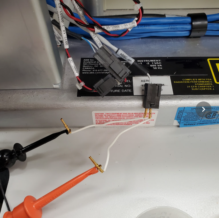
- Locate the ABBC SP and HBBC SP cables, that would normally connect to the blackbody controllers (ABBC SP is shown in Fig. 1). These are typically white cables with a 3-pin microfit connector, and are near the location of the blackbody controller boards
- Power ON the AERI instrument, but leave the laptop powered OFF
- Measure and record the DC voltage between the two pins on the ABBC SP cable. Measure and record the DC voltage between the two pins on the HBBC SP cable (see Fig. 1)
- Power ON the laptop. Wait for the Ingest software to start and for data to start getting collected (H1, A1, S1, etc. starts scrolling)
- Repeat the measurement of the DC voltage between the two pins on the ABBC SP cable, and the two pins on the HBBC SP cable
- Stop Ingest (Press <ctrl>+C repeatedly in the black cygwin window until the process stops, then close the FTSW window. Wait a few seconds to confirm that Ingest is stopped)
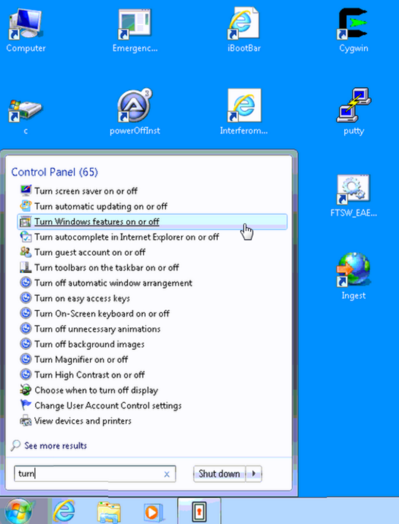
- In Windows, click Start, then type “turn” in the Windows search bar, then click on “Turn Windows features on or off” (see Fig. 2)
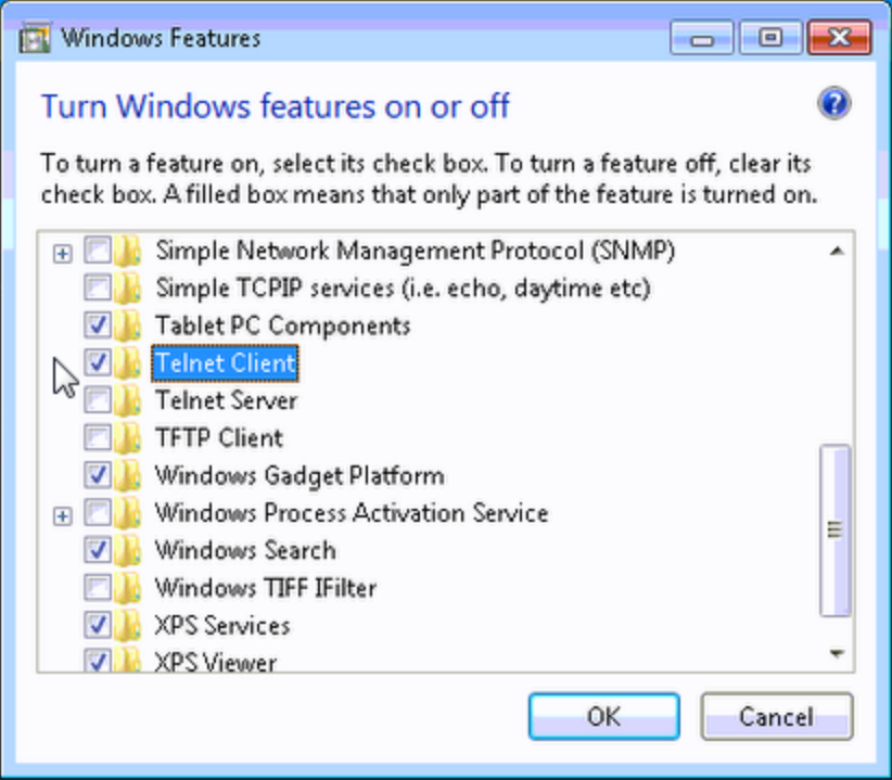
- In the Windows Features box that comes up, scroll down and click the check box to enable “Telnet Client“, then click OK (see Fig. 3)
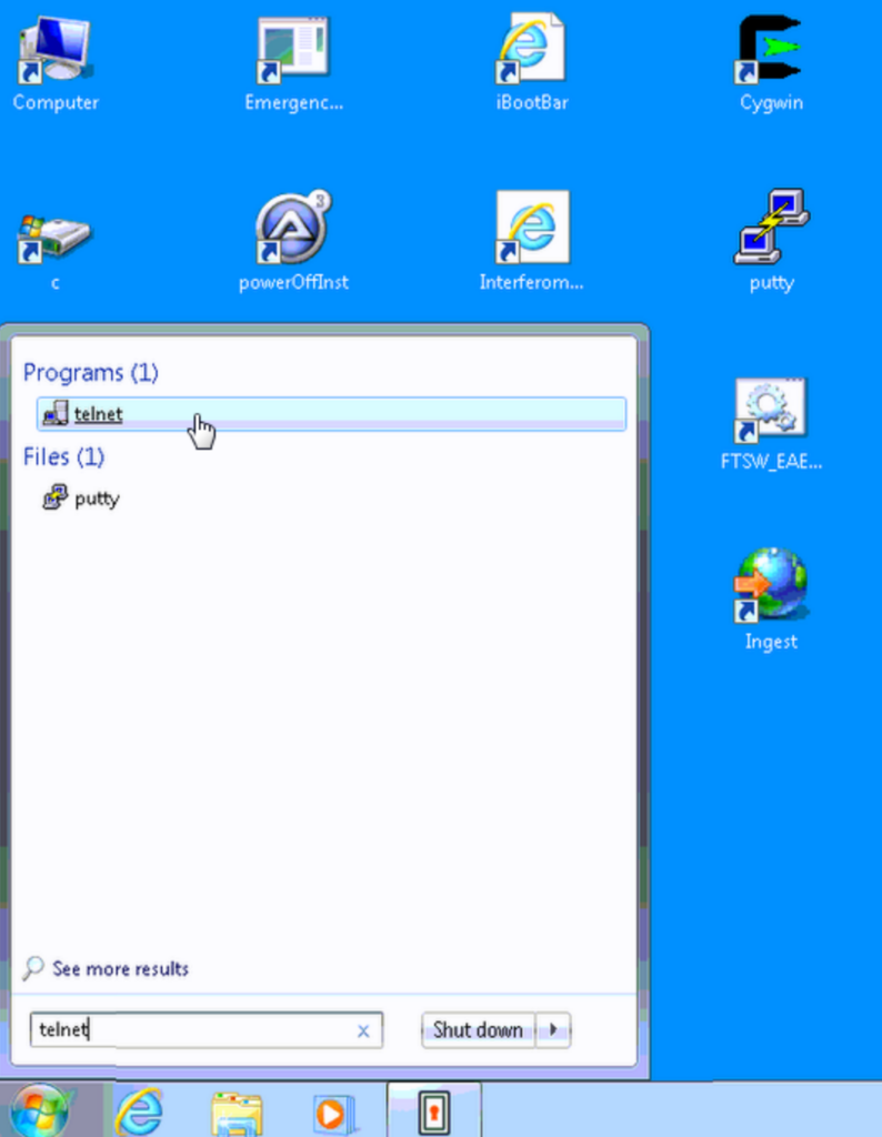
- In Windows, click Start, then type “telnet” in the Windows search bar, then click on “Telnet” (see Fig. 4)
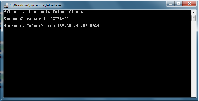
- At the telnet prompt type “open 169.254.44.52 5024” (see Fig. 5). This should result in a prompt for the L4400 Series. If the connection fails, just try again
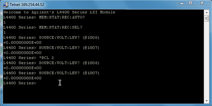
- At the L4400 Series prompt type the following seven commands, then take a screenshot of the results at the end, as shown in Fig. 4. If the result doesn’t appear immediately, then type <enter> and try the command again
- MEM:STAT:REC:AUTO?
- MEM:STAT:REC:SEL?
- SOURCE:VOLT:LEV? (@1006)
- SOURCE:VOLT:LEV? (@1007)
- *RCL 2
- SOURCE:VOLT:LEV? (@1006)
- SOURCE:VOLT:LEV? (@1007)
- Close the telnet session by typing <ctrl>+]
- Repeat the procedure for both the AERI-117 and AERI-118
- For both the AERI-117 and AERI-118, send the following information to the AERI team at the University of Wisconsin – Madison:
- DC Voltage on ABB SP connector with laptop OFF (from Step #4)
- DC Voltage on HBB SP connector with laptop OFF (from Step #4)
- DC Voltage on ABB SP connector with Ingest running (from Step #6)
- DC Voltage on HBB SP connector with Ingest running (from Step #6)
- Screenshot of telnet session (from Step #12)
- copy of the file: C:\E-AERI\agilent.config
- copy of the file: C:\E-AERI\FTSW_EAERI.Config