[Section 3] [Home] [Section 5]
In this section we will use 3-D displays only, but we'll not restrict our discussion to functions involving only three RealTypes. We shall also introduce a few other VisAD widgets.
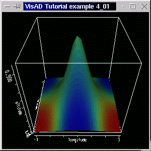
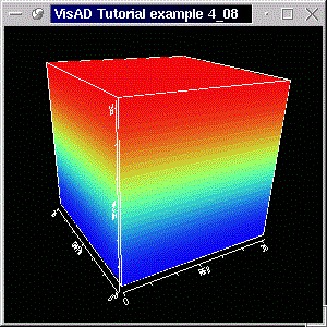
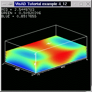
We want to display altitude in the z-axis and color the surface according to the temperature. To to that, first we need a display which has a z-axis:( (latitude, longitude) -> (altitude, temperature) )
display = new DisplayImplJ3D("display1");
The difference to the 2-D displays used so far isn't, well, only the "3", indicating it's a 3-D display. In fact, you might try changing the 2-D to a 3-D display in the previous example programs to see the difference. The lines and planes of the examples seen so far would simply be drawn at z=0. Three-dimensional displays have a third spatial dimension, and therefore allow for other DisplayRealTypes, that is, allow for different data depictions. To map altitude to z-axis we create the ScalarMapsimport visad.java3d.DisplayImplJ3D;
and we color the surface according to the temperature:altZMap = new ScalarMap( altitude, Display.ZAxis );
We add these maps to the display and do the rest as usual.tempRGBMap = new ScalarMap( temperature, Display.RGB );
Running the program will generate a window with a 3-D display like below:
A 3D display allows more DisplayRealTypes than a 2D display does and has other behavior, too. By dragging the left mouse button on the display you can rotate the cube. Dragging with the left mouse button and with the shift key pressed zooms the scene in and out. Dragging with the control key pressed tranlates the scene. Pressing and dragging the middle mouse button (on two-button mouse emulated by simultaneously clicking both buttons) shows a 3-D cross cursor that moves with the mouse. The values of the RealTypes at the cursor's position are shown on the upper left corner of the display.
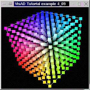
You have seen how easy it is to jump from 2-dimensional to 3-dimensional data depiction. You might try experimenting with other DisplayRealTypes. The code for this example already includes the ScalarMaps
Of course, you need to add them to the display, and have the other ScalarMaps not added. (By the way, you can clear the maps associated with a display by calling the display method clearMaps(). But first you need to remove the references, which can be done with the display methods removeAllReferences() or removeReference( ThingReference ref ).) Implementig the changes, compiling and running the example will generate a screenshot like below.altRGBMap = new ScalarMap( altitude, Display.RGB ); tempZMap = new ScalarMap( temperature, Display.ZAxis );
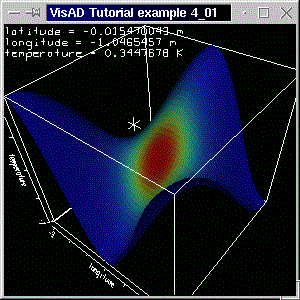
Note the cursor showing the coordinates with units. You can, off course, color the surface according to RealType that is mapped to the z-axis. Just use two ScalarMaps, with DisplayRealTypes ZAxis and RGB and the same RealType (temperature or altitude). Try doing these changes, it's worth it!
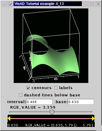
(don't forget that we have added the import statement: import visad.util.*; ) and created withContourWidget contourWid;
where tempIsoMap is temperature's IsoContour map. (You can only create a ContourWidget with an IsoContour map.) See the complete code here.contourWid = new ContourWidget( tempIsoMap );
Running the program will generate a window like the screen shot below:
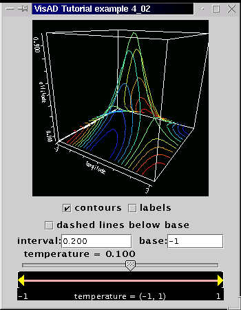
The ContourWidget allows for interaction regarding the isocontours. Not all switches are valid. Some of them only make sense with different types of data, as we shall see in section 4.12. Nevertheless, the ContourWidget is another nice tool in the visad.util package.
It should be clear by now how the ScalarMaps combined with the "right" DisplayRealTypes (that is, XAxis, YAxis, ZAxis, RGB, IsoContour, Red, Value, etc.) can give you the depiction you want.
In the next example we move on to another important topic: color control
Our example is a simplified version of the program of the previous section. We have the following MathType:
altitude is mapped both to ZAxis and to RGB. We have included the altitude values in the code. There are 6 (rows) times 12 (columns) altitude values in an array double[6][12]. Our domain set is the set( (latitude, longitude) -> altitude )
domain_set = new Linear2DSet(domain_tuple, 6000.0,     0.0, NROWS,
    					      0.0,  10000.0, NCOLS);
double[][] alt_samples = new double[][]{
  {3000.0,   3000.0,   6500.0,   4000.0,   3500.0,   4000.0,   5500.0,   4000.0,   4000.0,   4000.0,   5000.0,   1000 },
  {1000.0,   1500.0,   4000.0,   3500.0,   6300.0,   4500.0,   4000.0,   3800.0,   3800.0,   3800.0,   5000.0,   6400 },
  {  0.0,      0.0,       0.0,   1500.0,   3000.0,   6500.0,   4500.0,   5000.0,   4000.0,   3800.0,   3800.0,   6200 },
  {-3000.0,   -2000.0,   -1000.0,    0.0,   1500.0,   1000.0,   4000.0,   5800.0,   4000.0,   4000.0,   3900.0,   3900 },
  {-3000.0,   -4000.0,   -2000.0,   -1000.0,  0.0,   1000.0,   1500.0,   4000.0,   5700.0,   4500.0,   4000.0,   4000.0 },
  {-6500.0,   -6000.0,   -4000.0,   -3000.0,   0.0,   100.0,   1500.0,   4500.0,   6000.0,   4000.0,   4000.0,   4000.0 }};
This time we loop over rows and columns in a different way. We still have a 'flat' array: double[][] flat_samples = new double[1][NCOLS * NROWS]. The actual altitude values are put into this with two for-loops (as in the examples of section 3), but using an index variable, which "counts" the position of the samples in the flat array:
int index = 0;

for(int c = 0; c < NCOLS; c++)
  for(int r = 0; r < NROWS; r++){

    // set altitude
    flat_samples[0][ index ] = alt_samples[r][c];

    // increment index
    index++;
  }
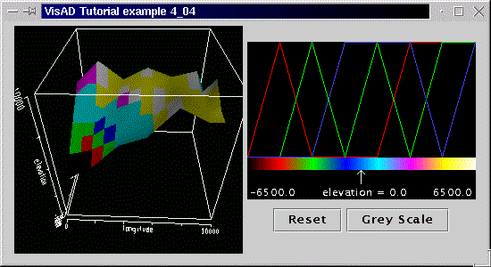
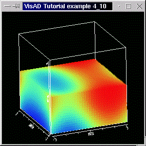
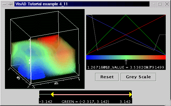
The interesting feature of this example, though, is the use of a LabeledColorWidget. This widget allows users to visualize how a RealType is mapped to a color table. Some direct manipulation of the color table is also possible.
To create such a cute widget simply do:
where altRGBMap is altitude's RGB ScalarMap. We then add the widget to the Java frame.labelCW = new LabeledColorWidget( altRGBMap );
The code for this example is available here. Running the program with "java tutorial.s4.P4_03" generates a window like the screen shot below.
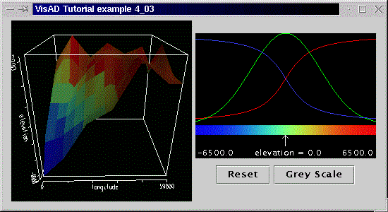
On the left we have the 3-D display, with altitude plotted against longitude and latitude. (Note that axes were auto-scaled.)
As already mentioned, the LabeledColorWidget allows interaction, too. The arrow just below the rainbow-colored bar can be moved by dragging with the left mouse button. The value of the RealType which is mapped to RGB and which is attached to the LabeledColorWidget is shown according to the arrow's position (note the that the altitude values vary from -6500 to 6500).
Above the bar you can see the distribution curves of the red, green and blue components. Click the left mouse button on a top part of the widget and drag to change either the red, green or blue distribution curves. The colored bar changes accordingly and so does the display. To switch between the color components click with either the middle or the right mouse button.
With the Reset button you can reset the color table and with the Gray Scale button you create a gray scale color table (that is, red, green and blue components increase linearly from 0.0 to 1.0).
Surely the LabeledColorWidget is a stunning widget, but there are times when you want to define your own color table. In the next example we'll show you how to do that.
    myColorTable = new float[][]{{0.0f, 1.0f, 0.0f, 0.0f, 0.0f, 1.0f, 1.0f, 1.0f},  // red component
     			         {0.0f, 0.0f, 1.0f, 0.0f, 1.0f, 0.0f, 1.0f, 1.0f},  // green component
     			         {0.0f, 0.0f, 0.0f, 1.0f, 1.0f, 1.0f, 0.0f, 1.0f}}; // blue component
As said, the values in the table are interpreted as red, green and blue components. (Remember, values range from 0 to 1.) The first color in the table is black: (r,g,b) = (0,0,0). The second color is red: (r,g,b) = (1,0,0). The following colors are green, blue, cyan, magenta, yellow and white.
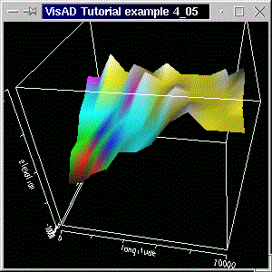
The actual difference to the previous example is in the constructor of the LabeledColorWidget:
The widget is created with our table as the initial color table.labelCW = new LabeledColorWidget( altRGBMap, myColorTable );
Please not too that we have set the ranes of the latitude and of the altitude map with the calls:
latMap.setRange(-2000.0f, 8000.0f);
altMap.setRange(-10000.0f, 10000.0f);
The code for this example is available here. Running the program with "java tutorial.s4.P4_04" generates a window like the screen shot below.
You can see the same surface and widget of the previous example. The colors, however, are those given by the color table. You can, off course, manipulate them with the help of the widget.
We use the same table of the previous example, but no LabeledColorWidget. To set the color table we first get hold of the ColorControl, from the RGB map:
and finally set the color table:colCont = (ColorControl) altRGBMap.getControl();
That was it! We changed the color without a widget.colCont.setTable( myColorTable );
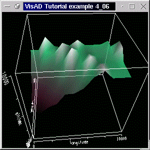
So that this example doesn't become boring, we make a call of a GraphicsModeControl's method. Remember from section 2.1 that we create a GraphicsModeControl with:
With the following call we disable texture mapping:GraphicsModeControl dispGMC = (GraphicsModeControl) display.getGraphicsModeControl();
dispGMC.setTextureEnable(false);
By disabling texture mapping we make the polygons have interpolated colors instead of textures. This removes the tesselated texture, like it was seen in the previous examples, and causes the smoother appearance.
The code for this example is available here. Running the program with "java tutorial.s4.P4_05" generates a window like the screen shot below.
The color table is the same as the one used in the previous example, but it has been implemented with the
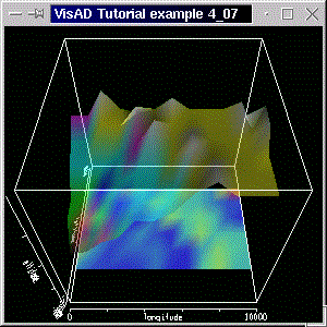
We simply decide that the higher our surface is, the more opaque (less transparent) it will be. This means, the higher the value of the RealType
and by adding it to the display, as usual.altAlphaMap = new ScalarMap( altitude, Display.Alpha );
In this section we also take the opportunity to show how you would create a color table using a loop. Our new colour table is given by an array float[3][ tableLength ]. We set the red (first) component of the table to decrease linearly (from 1 to 0) with the table length, the green (second) component to increase linearly (0 to 1), and set the blue (third) component to have a constant value of 0.5 (that is, 50% of maximum blue). Remeber, component values vary between 0 and 1. The code to create the table is as follows:
int tableLength = 10;

myColorTable = new float[3][tableLength];

for(int i=0;i < tableLength;i++){

  myColorTable[0][i]= (float) 1.0f - (float)i / ((float)tableLength-1.0f); // red component
  myColorTable[1][i]= (float) (float)i / ((float)tableLength-1.0f); // green component
  myColorTable[2][i]= (float) 0.50f; // blue component

}
myColorTable[0][9]=1.0f;
myColorTable[1][9]=1.0f;
myColorTable[2][9]=1.0f;
We implement the color change like we did in the previous section:
colCont = (ColorControl) altRGBMap.getControl();

colCont.setTable( myColorTable );
You can see the result of the use of a transparency map in the screenshot below and have a look at the code here.
In practice you might use alpha for modelling transparent clouds, or for making some soil layers transparent, so that you can see the other layers under them. In the next example we'll do that. We shall create another surface, based on the given data, and set the top layer with constant transparency, by using ConstantMaps.
Before we carry on, you might want to know that the LabeledColorWidget can be created with an RGBA (red, green, blue and alpha) map. The color-alpha table is then an array like float[4][length] and direct manipulation of the RGBA-table is possible.
Before we create the transparency ConstantMaps, we generate the other surface. We simply decide that we want a surface of the slope of the first surface in the x-direction (longitude). To put it mathematically correct, we want the first derivative of
Recall that we have the FunctionType
( (latitude, longitude) -> altitude )
In mathematical notation that reads altitude = f(latitude, longitude) (in words: altitude is a function of latitude and longitude), and we shall calculate slope = derivative of altitude with respect to longitude (we are assuming, for the sake of simplicity, that slope is measured in one direction olny).
We will need:
We start off by declaring the FlatField:
FlatField slope_vals_ff ;
To calculate the derivative we do hardly any work:
The line above means: calculate the derivative of altitude with respect to longitude, and assume no errors (that is, error mode is Data.NO_ERRORS; VisAD includes error propagation, which is calculated according to the chosen mode). Remember that in VisAD a FlatField represents a mathematical function, and thus is only natural that a FlatField would offer a mathematical operation such as differentiation. Note that the method returns a FlatField.slope_vals_ff = (FlatField) vals_ff.derivative( longitude, Data.NO_ERRORS );
If you are a bit lost, don't worry. You must bear in mind that, when we constructed the FlatField vals_ff for the altitude values with
we said how the function looks like: func_domain_alt is a function of domain (latitude, longitude) to altitude, and domain_set is the set which "says" how the data looks like. All the information is encapsulated in the FlatField. To make it a bit clearer, we get the function slope = f(latitude, longitude):vals_ff = new FlatField( func_domain_alt, domain_set);
FunctionType func_domain_slope = (FunctionType) slope_vals_ff.getType();
to get the range of this newly generated function (that is, the variable or variables which are a function of some other variables, also known in the mathematical jargon as "dependent variables"). The range is always a MathType (remember, the super class of RealType, RealTupleType, etc). For example, the range of the function ( (latitude, longitude) -> (altitude, temperature) ) is RealTupleType formed by altitude and temperature. In our case the range is simply slope, which is thus a RealType.RealType slope = (RealType) func_domain_slope.getRange();
Again, no mistery in the previous line. We are almost done, except by the DataReference.ScalarMap slopeRGBMap = new ScalarMap( slope, Display.RGB );
DataReferenceImpl data_ref2 = new DataReferenceImpl("data_ref2");
data_ref2.setData( slope_vals_ff );
ConstantMap[] constAlpha_CMap = { new ConstantMap( 0.50f, Display.Alpha) };
We choose to draw the slope's surface at a constant z value, that is at z = -1. This is done with the ConstantMap array:display.addReference( data_ref, constAlpha_CMap );
ConstantMap[] constZ_CMap = { new ConstantMap( -1.0f, Display.ZAxis)};
In the code, though, this is done in the inverse order. We first add the slope's reference and then the surface's reference.display.addReference( data_ref2, constZ_CMap );
The result can be seen in the following screenshot. The code for the application is, as usual, available here.
You can see the original surface, with the same colors as before, but with a constant transparency given by the constant alpha value map. The slope surface is drawn at a constant z = -1 value. (The cube has its center at (x,y,z) = (0,0,0) and side length equal to 2.)
It wasn't a straight forward matter to calculate the derivative. You might need to read this section again and also work through the code, till you can grasp what's been done. Nevertheless, you've met a very powerful method. Hopefully you'll realize how those Datamethods, used in conjunction with VisAD's MathTypes can simplify your work. Also try changing the values of the ConstantMaps and/or including a ConstantMap like ConstantMap( 3.50f, Display.PointSize ), like we did in section 2.4.
You could also add a ConstantMap alpha map to the whole display with
thus setting a constant transparency to all objects in the display.display.addMap( new ConstantMap( 0.50, Display.Alpha ));
Don't forget that you can add any number of references (data objects) to a display. In this section we added just another one, but we chose to introduce a method from FlatField class. This class includes other powerful methods like evaluate() and resample(), which can be used for evaluating the value of a function at a given value of the dependent variables and for interpolation, respectively.
In the next section we move on to consider 3-D sets in 3-D displays.
We start off by defining some RealTypes
red = new RealType("RED", null, null);
green = new RealType("GREEN", null, null);
blue = new RealType("BLUE", null, null);
The RealTypes are arbitrary and will be plotted in the x, y and z-axis.domain_tuple = new RealTupleType(red, green, blue);
The dependent variable is the RealType
rgbVal = new RealType("RGB_VALUE", null, null);
The RealTypes red, green and blue could be the dimensions of a space (like length, width and height) and the RealType rgbVal could be some quantity in this space, temperature, for example.
The function is defined as usual
and the number of samples in our "cube" as given byfunc_domain_rgbVal = new FunctionType( domain_tuple, rgbVal);
We then construct the set, with the number of samples aboveint NCOLS = 32; int NROWS = 32; int NLEVS = 32;
Note that we make no distiction between "number of samples" and "size of the cube", as we're dealing with an integer set. This is not the case for a linear set, where not only do you define the number of samples, but also the dimensions: starting at some value, and ending at some other value, with an arbitrary number of samples, as we shall see soon.domain_set = new Integer3DSet(domain_tuple, NROWS, NCOLS, NLEVS );
The next step concerns the actual values of rgbVal. We decide tht the higher the index of the sample, the higher the value
Those values fit in a "flat" array:
and they are set with the next following for-loopsdouble[][] flat_samples = new double[1][NCOLS * NROWS * NLEVS];
  int index = 0;

  for(int l = 0; l < NLEVS; l++)

    for(int c = 0; c < NCOLS; c++)

      for(int r = 0; r < NROWS; r++){

	    // set rgbVal values
	    flat_samples[0][ index ] =   index;

	    // increment index
	    index++;
    }
We've done this before, but in two dimensions. We then create the FlatField and feed it with the samples generated above:
vals_ff = new FlatField( func_domain_rgbVal, domain_set);

vals_ff.setSamples( flat_samples , false );
Rendering is given by the following choice of ScalarMaps:
Nothing new here either: domain types mapped to cube dimensions and color mapped to our independent variable. We add the maps to a 3-D display and do the other stuff as usual: set the Data Reference with the FlatField and add the reference to the display.redXMap = new ScalarMap( red, Display.XAxis ); greenYMap = new ScalarMap( green, Display.YAxis ); blueZMap = new ScalarMap( blue, Display.ZAxis ); rgbMap = new ScalarMap( rgbVal, Display.RGB );
The result can be seen in the following screenshot. The code for the application is available here.
The volume is colored according to the index. At the bottom of the cube, where index is low, we have blue (recal that the standard color table varies from blue, through green, to red), and at the top we have higher index values, and thus red.
In the next example we vary the choice of ScalarMaps and see what happens to the cube.
We have also choosen less samples (8 for each side).redMap = new ScalarMap( red, Display.Red ); greenMap = new ScalarMap( green, Display.Green ); blueMap = new ScalarMap( blue, Display.Blue );
You can now see the individual points (or voxels) of the Integer3DSet. We have made them bigger with the GraphicsModeControl's call:
dispGMC.setPointSize(40.0f);
Note that the color values are given by the respective values of the cube sides. From the distance, the displays shows a cube like the rgb-color-cube. If you zoom in (press shift key and left mouse button and move the mouse), you can see the individual voxels.
We still use the same RealTypes, domain, and FunctionType of example 4.8. The only difference is the different domain set:
domain_set = new Linear3DSet(domain_tuple,
                              -Math.PI, Math.PI, NROWS,
                              -Math.PI, Math.PI, NCOLS,
                              -Math.PI, 0,       NLEVS );
Note the use of upper and lower boundaries for all three dimensions.For the first two dimensions we have 32 samples for each dimension (given by NROWS and NCOLS). We have however only 16 samples for the number of levels (NLEVS), that is, for the RealType
blueZMap.setRange(-Math.PI, Math.PI );
If we hadn't done that, than the range of the
Also note that we got the set samples with the call
They were used to make some values up for the independent variable.float[][] set_samples = domain_set.getSamples( true );
As promised, we change the projection policy with the GraphicsModeControl:
dispGMC.setProjectionPolicy(DisplayImplJ3D.PARALLEL_PROJECTION);
The other valid projection policy is
You can have a look at the code which generates a figure like the screenshot below.
As said, the difference between a linear and an integer set is that the latter is an specialization the the former, in that its samples are a progression of integers. (But all other methods used for the display in this section apply equally for the integer set.)
Let's start with the color-alpha table. Remember, such a table looks like float[ 4 ][ tableLength ], that is red, green, blue and alpha components in the first dimension, and a number
int tableLength = 15;

myColorTable = new float[4][tableLength];

for(int i=0;i < tableLength;i++){

  myColorTable[0][i]= (float) i / ((float)tableLength-1.0f); // red component
  myColorTable[2][i]= (float) 1.0f - (float)i / ((float)tableLength-1.0f); // blue component

  if(i<(tableLength)/2){ // lower half of table

    myColorTable[1][i]= 2.0f *(float) i / (tableLength-1); // green component
    myColorTable[3][i]= 0.8f * myColorTable[0][i];

  }
  else{ // upper half of table

    myColorTable[1][i]=  2.0f - 2.0f *(float)i / ((float)tableLength-1); // green component
    myColorTable[3][i]= 0.8f * myColorTable[2][i];// alpha component

  }
}
No, we're not happy yet (but not because it's not confusing enough). We decide to give the aplha component a special look by doing:
The first two lines of code above make the first two values of the alpha component opaque. That is, the RealType linked to this RGBA map (and thus linked to the table) will have its lower values blue and opaque. The last two lines of code will make the data with highest values of the RealType red and "half-transparent".// make lower edge "sharp"; alpha values only myColorTable[3][0]= (float) 1.0f; // alpha component myColorTable[3][1]= (float) 1.0f; // alpha component // make upper edge semi-transparent; alpha values only myColorTable[3][13]= (float) 0.5f; // alpha component myColorTable[3][14]= (float) 0.5f; // alpha component
Let us not forget the LabeledColorWidget:
WherelabelCW = new LabeledColorWidget( rgbaMap, myColorTable );
(Remember,rgbaMap= new ScalarMap( rgbVal, Display.RGBA );
We have also promised a SelectRangeWidget. For that we need a ScalarMap with Display.SelectRange:
Yes, you guessed it right. The chosen RealType isgreenRangeMap = new ScalarMap( green, Display.SelectRange );
After adding the above map to the display, we create the SelectRangeWidget:
selRangeWid = new SelectRangeWidget( greenRangeMap );
and we're finished!
The complete code is available. Below is a screenshot of the program.
The first thing to notice on the picture above is that our former solid parallelepiped is now transparent (compare with the previous example). The degree of transparency is, however, not constant. It varies according to the alpha component of the color-alpha table (see the gray line of the LabeledColorWidget). As said, the LabeledColorWidget behaves as described in section 4.3, but now you can manipulate all 4 components of the table.
The SelectRangeWidget allows you to select the range in which the RealType
We use the previous example and make no changes to its data structure. The only change we make regards the boundaries of the set, which are now
domain_set = new Linear3DSet(domain_tuple,
                            -Math.PI, 2.0*Math.PI, NROWS,
                            -Math.PI, Math.PI, NCOLS,
                            -Math.PI, 0.0,     NLEVS );
First we get the ProjectionControl:
To change the aspect ratio we define an array with the ratiosProjectionControl projCont = display.getProjectionControl();
double[] aspect = new double[]{1,0.66,0.33};
We get the projection matrix withprojCont.setAspect( aspect );
Running the code, the 16 values of the matrix get printed out in the command window. There's also a matrix in the code, which can be used to set a new projection. Just uncomment the necessary line.double[] projMatrix = projCont.getMatrix();
The complete code is available. Below is a screenshot of the program.
Note that the ProjectionControl can also be used for 2-D displays. In this case, the matrices are an array like double[1][6]. The 3-D case uses matrices with 16 elements, in an array double[1][16]. The aspect ratio of 2-D displays is given by arrays like double[1][2].
Changing the aspect ratio implies a change in the projection matrix. The matrix that is printed out in this example is the transformed matrix. A value greater than one in the aspect ratio array means a magnification. That's why we chose 1,0:0,66:0,33, rather than 3:2:1 (but you can try changing those values!). Finally note that by changing the aspect ratio, you change the shape of the cursor.
We need a ScalarMap with IsoContour, off course:
As you see, we'll draw the isocontours of the RealType rgbVal. As our set is 3-dimensional, we don't expect to see isolines, but isosurfaces. That is, surfaces which have the same rgbVal value. We'll control this value with the help of the ContourWidget.rgbIsoMap = new ScalarMap( rgbVal, Display.IsoContour );
Dont' forget to add the map to the display before we create the ContourWidget as follows:
contWid = new ContourWidget(rgbIsoMap);
The complete code for this example is available here. Below is a screenshot of the application.
You can change the value of the isosurface by moving the slider. The data of this example is the same as that of the previous example (just some set boundaries were changed, and the aspect ratio change was removed). By adding the IsoContour ScalarMap, you can drastically change data depiction without changing the way your data is organized (as you probably know by know)
In this section we take it easy and take the opportunity to introduce a few DisplayRenderer methods. The DisplayRenderer is the superclass for background and metadata rendering algorithms. There are a few of those in VisAD, and we'll come across some of them, later on in the tutorial. For now we are only interested in grabbing the DisplayRenderer of a display, and calling a few methods to change colors, turn off the display box and so on. It's also a good opportunity to change axes colors and names, while we are on the subject of display layout.
We take the last example and adapt it a bit to show some interesting methods. First we get the DisplayRenderer with
and the first useful thing we do with it is to set the background color:DisplayRenderer dRenderer = display.getDisplayRenderer();
dRenderer.setBackgroundColor(Color.white);
Note that you can also change the foreground color, which will change both the axes, the box and the cursor colors.
dRenderer.setForegroundColor(Color.gray);
With the DisplayRenderer we can also turn the box off:
dRenderer.setBoxOn( false );
Although we haven't done it in the example (the code line is commented out), you might want to change the box color:
dRenderer.setBoxColor(Color.gray);
The second change regards axes names. When a ScalarMap is created, it uses the name of the ScalarType as the axis label (in case is a map to one of the axes). This works fine, but has the disadvantage of not allowing some characters (as there are some constraints on a ScalarType's name). Furthermore, you might want to write a little more on the axis as only the name of the ScalarType. To set the axis label you call the ScalarMap method:
redXMap.setScalarName("The RED Component");
To change the color of an axis, you can do
Note that r is a float with RGB components between 0 and 1. The method colorToFloats(Color c) is just a convenience method to decompose a java.awt.Color into its RGB components. It returns a float array like float[]{ red, green, blue}, with values between 0 and 1. The method is included in the code for this example.float[] r = colorToFloats(Color.red); redXMap.setScaleColor( r );
Although
You can see the results in the following picture. The complete code for this example is available here.
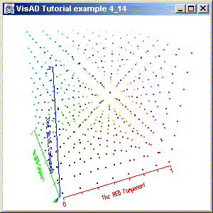
Note that each axis has its own color, and also has a customized label. The background color is somewhat dull, but you can choose your own color. Finally, the box is nowhere in sight, but now you know how to turn it on and off and know how to change its color.
In the next section we consider animation with VisAD.